81
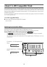
Measurement Section
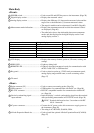
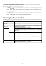
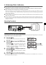
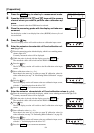
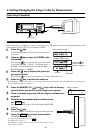
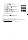
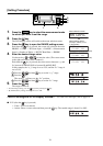
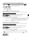
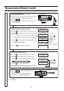
DARKEN PROBE
PUSH 0-CAL KEY
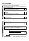
ZERO CALIBRATION
CH00 EXT Ad P1
[ ]
CH01 EXT P3
[ ]
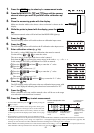
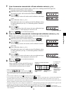
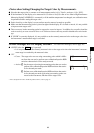
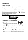
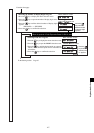
MENU : SELECT
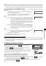
PUSH SPACE KEY
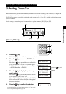
SELECT : PROBE
P1 35881112
SELECT : PROBE
P3 35881113
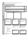
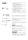
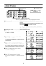
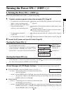
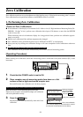
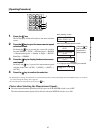
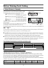
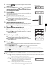
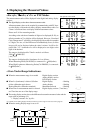
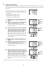
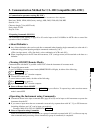
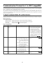
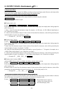
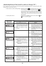
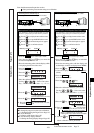
Message displayed
when the POWER
switch is set to ON
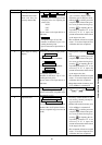
Press the 0-CAL key.
During zero calibration
End of zero calibration
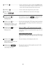
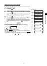
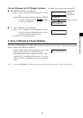
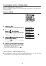
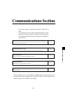
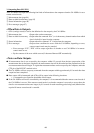
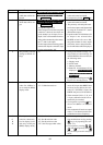
Memory channel Probe no.
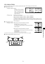
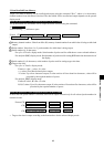
Menu selection screen
PROBE selection screen
Probe no.
Press the
key until the
desired probe
no. appears.
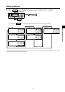
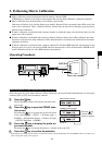
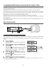
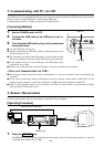
[Operating Procedure]
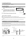
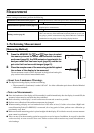
1. Set the POWER switch to ON.
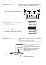
2. Place receptor area of measuring probe
face down on a flat surface so that no light
reaches the receptor area.
Never direct the measuring probe toward a high-lumi-
nance illuminant.
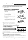
When the optional 4-Probe Expansion Board CA-B04 is used
Block the receptor of each measuring probe from light.
If there are any receptors not blocked from light, zero
calibration will not be performed correctly.
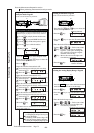
3. Press the 0-CAL key.
4. Press the MODE key to select analyzer
measurement mode (RGB).
5.Press the MEMORY CH and keys
to select the memory channel for which the
RGB emission characteristic for analyzer
mode has been set (page 58).
When the optional 4-Probe Expansion Board CA-B04 is used
Select the probe no. for which the RGB emission characteristic for the analyzer mode has been input.
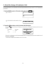
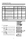
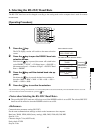
1 Press the key.
The LCD display section will switch to the menu selection screen.
2 Press the key to open the PROBE selection screen.
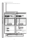
Each time the
key is pressed, the screen will switch in the
order PROBE → SYNC → ID Name input → RANGE → Mea-
surement Speed → Number of Digits → RS232C Baud Rate →
PROBE.
3 Press the key to display the probe no. you want to select.
Each time the
key is pressed, the probe no. switches in the
order [P1] ….
4 Press the key to confirm the selection.
* By default (factory setting), the instrument is set so that [P1] will be selected automati-
cally when the POWER switch is set to ON. If you want to change this setting, refer to
page 30.
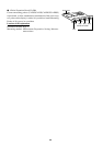
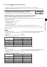
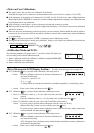
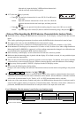
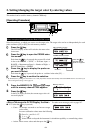
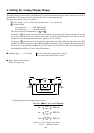
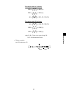
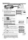
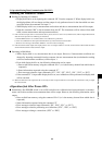
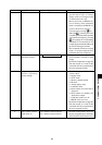
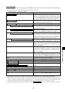
6. Place the receptor area of the measuring probe flat
against the surface of the display to be measured.
Measurements will be started immediately and mea-
sured data will be shown in the digital and analog
displays.
Block entry of light
Place the probe with the display