


96
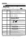
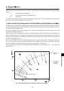
3. Status Information
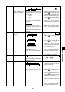
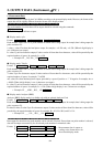
Inputting the command “Z” will cause the present settings and status of the CA-100Plus to be output as a 134-
character word as shown below.
Format: display mode SYNC mode memory channel number and ID name analog display range
luminance unit probe number for display probe number for output calibration mode on/off in analyzer mode
WRGBvalues input status delimiter
• In the following, “_” indicates a space.
Example: MODE : RGB _ _ _ _ _ SYNC : NTSC_ _ _ CH01 [MINOLTA _ _ _ ] _ _ _ RANGE _ _ R : 1.0% _ GB : 2.0% _ _ _ LUMI. : cd/
m*m _ _ _ _ _ _ _ DISP - P : 1 _ _ _ OUT - P : 135 _ _ _ _ _CAL : ON_ _ _ _ W : * _ R : * _ G : _ _ B : * _ delimiter
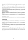
Content
Display mode
SYNC mode
Memory channel
number and ID name
Analog display range
Luminance unit
Probe number for
display
Probe number for
output
Calibration mode on/
off in analyzer (RBG)
display mode
WRBG values input status
Number of
characters
13
12
19
24
15
11
14
10
16
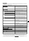
Format
MODE : xyY _ _ _ _ _ (For xyLv display mode)
MODE : T∆uvY _ _ _ (For T∆uvLv display mode)
MODE : RGB _ _ _ _ (For analyzer (RBG) display mode)
In example, display mode is set to analyzer (RBG) display mode.
SYNC : NTSC _ _ _ (For NTSC mode)
SYNC : PAL_ _ _ _ (For PAL mode)
SYNC : EXT_ _ _ _ (For EXT mode)
SYNC : UNIV _ _ _ (For UNIV. mode)
SYNC : INT_ _ _ _ (For INT mode)
In example, SYNC mode is set to NTSC.
CH memory channnel number [ ID name ] _ _ _
Memory channel number: Two characters
ID name: Ten characters
In example, memory channel 01 is selected and ID name is “MINOLTA”.
RANGE _ xy : range % _ _ Y : range % _ _ _ (For xyLv or T∆uvLv display mode)
RANGE _ _ G : range % _ RB : range % _ _ _ (For analyzer (RBG) display mode; G reference)
RANGE _ _ R : range % _ GB : range % _ _ _ (For analyzer (RBG) display mode; R reference)
Range: Three characters; if actual value fewer than three characters, value will
be preceded by required number of spaces.
In example, analog display range for R is set to1.0% and the range for B and G is set to 2.0 %.
LUMI. : cd/m*m _ _ _ (For cd/m
2
)
LUMI. : fL _ _ _ _ _ _ _ (For fL)
In the example, the luminance unit is fL.
DISP - P : probe number for display _ _ _
Probe number for display: One character; 1 to 5
In example, probe number P1 was selected for display.
OUT - P : probe number for display _ _ _
Probe numbers for output: Up to five characters; 1 to 5; if fewer than five
characters, remaining characters will be spaces.
In example, probe numbers P1, P3, and P5 were selected for output.
CAL : ON_ _ _ _ (If calibration mode on)
CAL : OFF_ _ _ (If calibration mode off)
In example, calibration mode for analyzer mode is on.
W: # _ R : # _ G : # _ B : # _
# : * if value has already been input;_ if value has not been input yet
In example, values for W, R, and B have been input but value for G has not been input yet.
*1: Calibration mode on/off in analyzer (RBG) display mode will be output only when analyzer (RBG) display mode is set.
*2: WRBG values input status will be output only when calibration mode is on in analyzer (RBG) display mode.
*1
*2