55
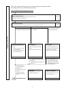
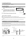
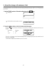
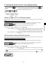
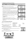
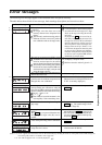
Settings Section
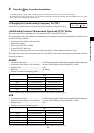
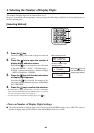
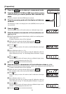
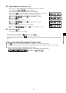
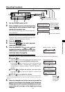
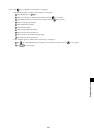
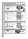
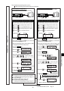
7. Enter the emission characteristic of B and calibration values (x, y, Lv).
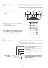
1 Place the measuring probe with the display, which is now emitting monochrome light of B.
Currently measured values will be displayed.
2 While the probe is placed with the display, press the HOLD key.
The measured values will be hold and the HOLD LED lights up.
3 Press the key.
The LCD display section will switch to the B calibration value input
screen.
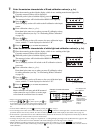
4 Enter calibration values (x, y, Lv).
Enter them in the same way as when you enter W calibration values
for white calibration (see step 7 in “Performing White Calibration”
on page 52).
5 Press the key.
The LCD display section will return to the user calibration input
screen, with the “*” mark displayed on the left of “B”.
6 Press the HOLD key to resume measurement.
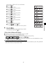
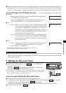
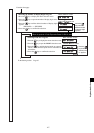
8. Enter the emission characteristic of white light and calibration values (x, y, Lv).
1 Place the measuring probe with the display, which is now emitting white light.
Currently measured values will be displayed.
2 While the probe is placed with the display, press the HOLD key.
The measured values will be hold and the HOLD LED lights up.
3 Press the key.
The LCD display section will switch to the W calibration value in-
put screen.
4 Enter calibration values (x, y, Lv).
Enter them in the same way as when you enter W calibration values
for white calibration (see step 7 in “Performing White Calibration”
on page 52).
5 Press the key.
The LCD display section will return to the user calibration input
screen, with the “*” mark displayed on the left of “W”.
6 Press the HOLD key to resume measurement.
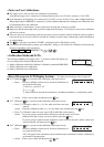
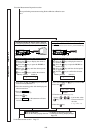
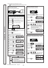
9. Press the key.
Matrix calibration will start, and the W measured
values entered at step 8 will be set as the target
color when the correction factor is entered.
* Steps 5 to 8 can be performed in any order.
* Pressing the
, , or key before pressing the key
at step 9 allows you to re-enter the emission characteristic of the
color or the measured values of white light and calibration val-
ues.
*To cancel matrix calibration, press the
key before pressing the key at step 9.
*
To view the target color values set for matrix calibration, press the MR key. However, if the target color is set after matrix calibration is
performed with the same memory channel, the values for that target color set last will be displayed. (For details, refer to page 72.)
* If measurement is performed with non-user-calibrated memory channel for the first time since shipment from the factory, the Konica
Minolta’s calibration standard will be used for the measurement.
*To change the target color you set, change it as explained in “1. Setting/Changing the Target Color by Measurement” (page 62). The
currently set correction factor for matrix calibration will remain unchanged even if the target color is changed.
*
Matrix calibration can still be performed even if the measured values are not hold (i.e. even if the HOLD key is not pressed).
In this case, the measured values confirmed by pressing the
key at steps 5 to 8 will be used for calculation of the correction factor for
matrix calibration.
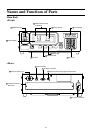
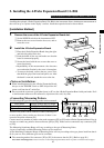
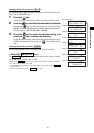
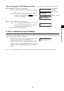
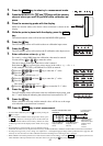
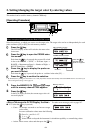
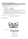
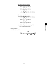
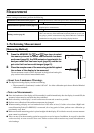
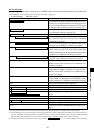
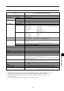
x
y
Lv
∆x
∆y
∆Lv
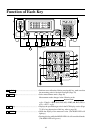
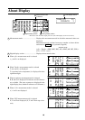
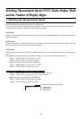
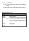
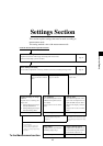
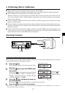
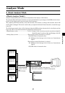
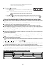
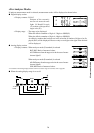
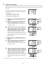
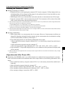
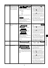
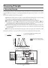
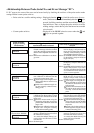
LCD display section:
Memory channel
Measurement speed
Calibration mode
Probe no.
ID name
Example of screen after matrix
calibration
Digital display section:
Displays calibration
values.
Analog display section:
Displays the center
dots only.
“m” is displayed after
matrix calibration.
“
*
” mark is displayed.
“
*
” mark is displayed.