


90
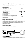
Communication Format for CA-100 Compatible
To use the instrument in the same communication environment as CA-100, make sure that “CA-100 compatible
mode”, “FAST mode” and “3-digit display mode” are selected.
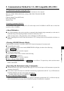
The commands listed in the following tables can be used to control in the CA-100 Compatible. Most of the com-
mands listed are applicable to data communication with RS-232C system; those that are applicable to only one
system are indicated as such.
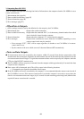
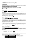
1. Input Command Table (PC
→ →
→ →
→ Instrument)
Inputting commands shown in the table below will operate the instrument in the same way as when the correspond-
ing keys are pressed.
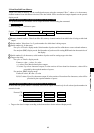
Terms used in the table
Display probe no. Indicates the probe no. whose measured data is displayed.
Output probe no. Indicates the probe no. whose measured data is to be output.
CAL mode Indicates that the
key has been pressed.
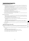
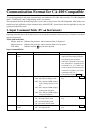
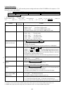
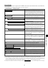
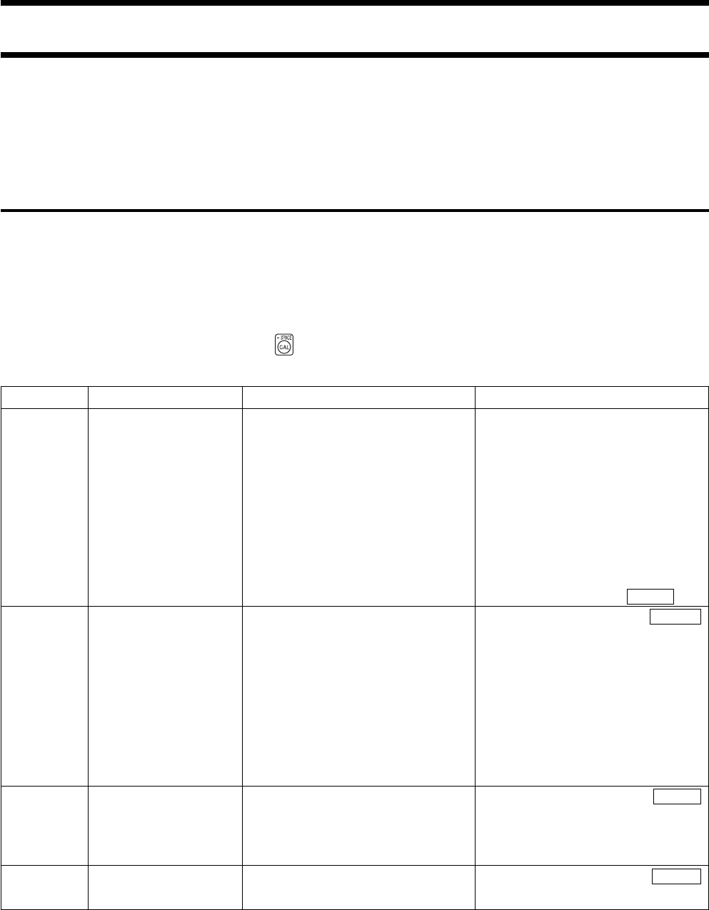
Input Command Table
Command
I
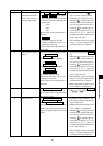
M
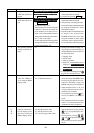
S
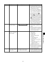
H
Function
Performs zero calibra-
tion
Selects display mode
Selects SYNC mode
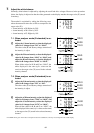
Sets/cancels display
hold
Input format
“I”
“M0”: Sets xyLv display mode
“M1”: Sets T∆uvLv display mode
“M2”: Sets analyzer (RGB) display
mode (analog display is not
lit).
“M3”: Sets analyzer (RGB) display
mode (green-reference).
“M4”: Sets analyzer (RGB) display
mode (red-reference).
“S0”: Sets NTSC SYNC mode
“S1”: Sets PAL SYNC mode
“S2”: Sets EXT SYNC mode
“S3”: Sets UNIV. SYNC mode
“H0”: Cancels display hold
“H1”: Sets display hold
Further information
• Block all light from reaching the re-
ceptor area of measuring probes be-
fore inputting this command.
• Until this command is input and
zero calibration is completed, the
commands U, A, N, J, and E will
not be accepted. (Do not string the
command I together with other
commands using “&”.)
• Corresponds to pressing 0-CAL key.
• Corresponds to pressing MODE
key.
• Corresponds to pressing SYNC
key.
• Corresponds to pressing HOLD
key.