


2828
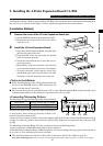
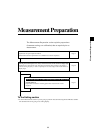
3. Connecting the Power
Power voltage range for the instrument — 100 to 240V
[Connection Method]
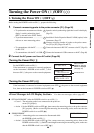
1. Set the POWER switch to OFF (“O” posi-
tion).
2. Connect the AC power cord’s connector to
the AC power connector on the instrument.
The AC power cord must be connected as shown in the
figure.
3. Insert the AC power cord’s plug to an AC outlet.
<Notes on Power Connection>
● Never connect or remove the AC power cord while the POWER switch is ON.
● When connecting/disconnecting the AC power cord, always hold the plug and connect/disconnect it. In addi-
tion, do not pull or bend the cord excessively or exert excessive force on it. Doing so may result in wire
breakage.
● Be sure to connect the AC power cord's plug to an AC outlet that has a protective grounding terminal.
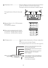
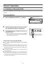
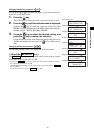
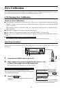
4. Inputting the Vertical Synchronizing Signal
The vertical synchronizing signal from the display can be input to the instrument to allow synchronous measure-
ment (when EXT SYNC mode is selected).
However, if another SYNC mode is selected, it is not necessary to input the vertical synchronizing signal.
Connect the BNC cable of the vertical synchronizing signal (frequency: 40 to 200 Hz) used for the display to the
connector on the rear panel of the instrument as shown below. Before connecting, make sure that the power to both
the instrument and display is turned OFF.
3
2
Main body
AC power connector
To an AC outlet
AC power cord
* To synchronize measurement with the display’s vertical synchronizing signal, EXT must be selected as the SYNC mode. For details, refer
to page 36.
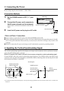
Circuit diagram
1
2
74HC14
(operated with 5V)
Vertical synchronizing
signal input terminal
Connector type: BNC
C-MOS logic level
Input the vertical
synchronizing signal.
(40 to 200 Hz)
BNC connector