97
Communications Section
4. Error Messages
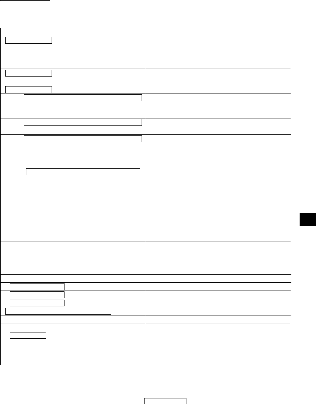
Error messages which may be output by the CA-100Plus when remote-control mode has been set are listed below.
* For information on error messages which may appear in the LCD, see page 107.
• In the following, “_” indicates a space.
Error message format
Measurement data _ P
Measurement data _ T
Measurement data _ F
E3 _ _ ; command which caused error (up to 20 characters)
E4 _ _ ; command which caused error (up to 20 characters)
E5 _ _ ; command which caused error (up to 20 characters)
E10 _ _ ; command which caused error (up to 20 characters)
E11
E12
E13
E20
E21
P probe number (1 to 5) _ E22
P probe number (1 to 5) _ E23
P probe number (1 to 5) _ E24;
Luminance value Lv (up to four characters)
E25
E26
P probe number _ E28
E29
E30
Explanation
Present measuring probe and measuring probe used for cali-
bration to a user-selected reference or for setting target color
(or for inputting RGB emission characteristics of the display
in analyzer mode) are different. (LCD error message: E1)
Ambient temperature has changed since zero calibration
was performed. (
LCD
error message: E2)
Measured data is outside of measuring range. (Digital display blinking)
Error in setting calibration values for user-selected refer-
ence. Remote-control mode canceled; new or additional
commands not accepted.
0% was set as analog display range. Remote-control mode
canceled; new or additional commands not accepted.
The command “E” was input before acceptable data was in-
put for all four values (R, G, B, and W) when inputting RGB
emission characteristics for
the display
. Remote-control mode
canceled; new or additional commands not accepted.
The input command is not acceptable. Remote-control mode
canceled; new or additional commands not accepted.
A command string of more than 250 characters was input.
Remote-control mode canceled; new or additional com-
mands not accepted.
Error in RS-232C data communication. A command was
input while CA-100Plus was unable to accept commands.
Remote-control mode canceled; new or additional com-
mands not accepted.
The command “E” was input to input the target color (W)
while “OVER” was displayed in the LCD. Remote-control
mode canceled; new or additional commands not accepted.
LCD error message: NO SYNC. SIGNAL
LCD error message: TOO BRIGHT
LCD error message: OVER
LCD error message: OFFSET ERROR PUSH 0-CAL KEY
Measured value is over display range in T∆uvLv display
mode.
LCD error message: SET MAIN
LCD error message: PROBE ERROR PROBE
LCD error message: DATA ERROR
LCD error message: DARKEN PROBE
LCD error message: DARKEN PROBE PUSH 0-CAL
KEY
*1: If the conditions for more than one of these error messages occur, the appropriate error messages will be strung together.
*2: If the conditions for any of these messages occur, the appropriate error message will be output continuously as long as the power is on,
and new or additional commands will not be accepted. If this occurs, switch power off and then switch it on again. (When performing
RS-232C data communication, these messages will be output regardless of whether remote-control mode is on or off.)
For example, if the conditions for all three error messages occurred: Measurement data _ P _ T _ F would be output as the error message.


