48
Before Making Each Setting
1. About Memory Channels
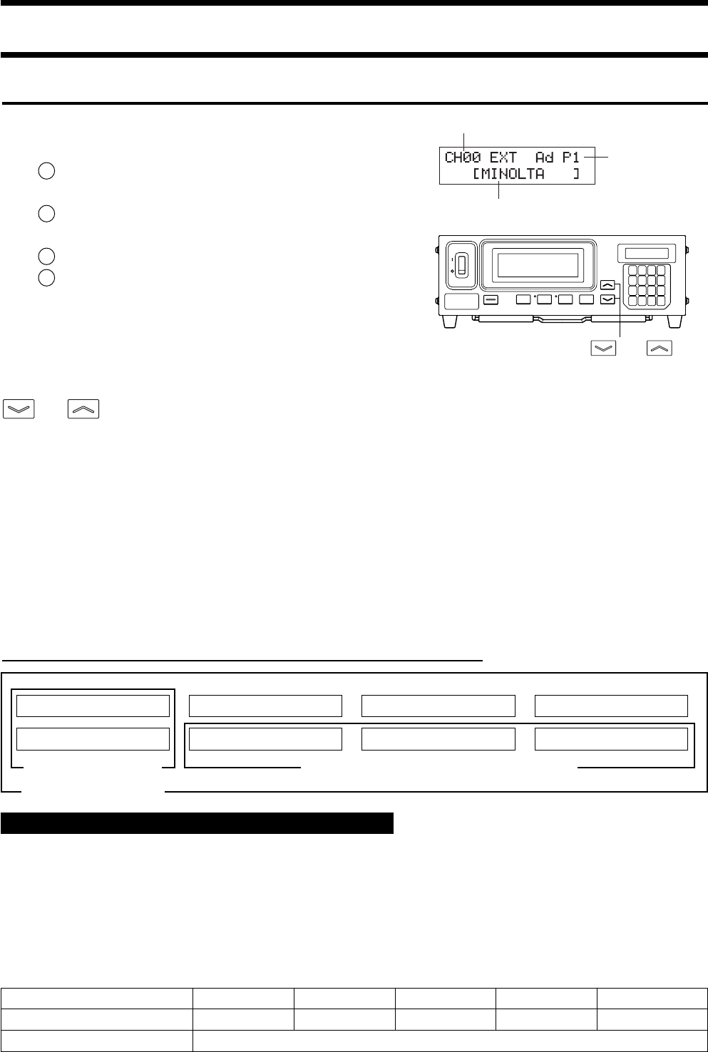
This instrument has a total of 100 channels (CH00 to CH99).
The following items can be set for each of these channels.
1 Correction factor for user calibration ...........................
.................................... (For details, refer to page 50.)
2 RGB emission characteristic for analyzer mode .............
.................................... (For details, refer to page 58.)
3 Target color .................... (For details, refer to page 48.)
4 ID name .......................... (For details, refer to page 66.)
CH00 is provided for calibration that uses Konica Minolta’s cali-
bration standard.
For this channel, only the target color, RGB emission characteris-
tic for display’s analyzer mode and ID name can be set.
The desired memory channel can be selected by switching from one to another by pressing the MEMORY CH
and keys.
It is also possible to assign an ID name to each memory channel by entering it directly using keys. The ID name is
displayed together with the memory channel no. in the LCD display section.
● If the RGB emission characteristic for analyzer mode is input using a memory channel that has been matrix-
calibrated, the correction factor for matrix calibration will be deleted. (If xylv, T∆uvLv, u'v'Lv or XYZ mea-
surement mode is selected, the Konica Minolta’s calibration standard will be used for measurement.)
● In the case of the same memory channels and probes, the RGB emission characteristic for analyzer mode is
stored in their common memory irrespective of measurement mode. Therefore, when matrix calibration is
performed, the RGB emission characteristic for analyzer mode is also input at the same time.
User Calibration How the memory is used in the case of analyzer mode
Probe no.
Memory channel
ID name
MEMORY CH
and keys
Calibration values xyLv for W Calibration values xyLv for R Calibration values xyLv for G Calibration values xyLv for B
Measured value for W Measured value for R Measured value for G Measured value for B
Used for white calibration Used for analyzer mode RGB emission characteristic
Used for matrix calibration
When the optional 4-Probe Expansion Board CA-B04 is used
<Relationship between Memory Channels and Probes>
If the 4-Probe Expansion Board is installed, each probe ([P1] to [P5]) has a total of 100 channels (CH00 to CH99).
The correction factor for user calibration (1), RGB emission characteristic for analyzer mode (2) and target color (3) can
be set for each probe. However, ID name (4) is common to all the probes of the same memory channels.
For instance, if the ID name “CRT-001” is assigned to CH01 when the measured values for probe [P1] are displayed,
“CRT-001” will be displayed for CH01 of all the probes [P1] to [P5].
Probe no. [P1] [P2] [P3] [P4] [P5]
Usable memory channels CH00 to 99 CH00 to 99 CH00 to 99 CH00 to 99 CH00 to 99
ID name (page 66) CH00 to 99 (Common to all probes)


