


40
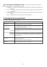
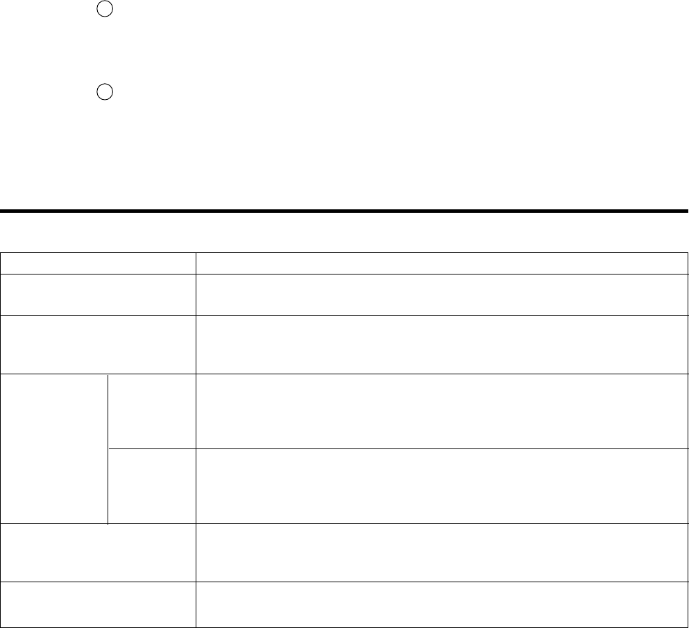
Measurement Mode Description
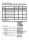
xyLv mode
Used to display/output chromaticity coordinates xy and luminance Lv.
(The analog display section shows ∆x, ∆y and ∆Lv.)
T∆uvLv mode
Used to display/output T (correlated color temperature), ∆uv (color difference from
blackbody locus) and luminance Lv.
(The analog display section shows ∆x, ∆y and ∆Lv.)
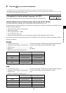
Analyzer mode
G-reference
Used to display meeasurement RBG emission luminances as a percentage of the RGB
emission luminances target color(W). Analog display shows measured ratios R/G and
B/G, and ∆G
R-reference
Used to display meeasurement RBG emission luminances as a percentage of the
RGB emission luminances target color(W). Analog display shows measured ratios G/
R and B/R, and ∆R
u'v'Lv mode
Used to display/output u'v' chromaticity coordinates (CIE 1976 UCS chromaticity
diagram) and luminance Lv.
(The analog display section shows ∆x, ∆y and ∆Lv.)
XYZ mode
Used to display/output tristimulus values X, Y and Z.
(The analog display section shows ∆x, ∆y and ∆Lv.)
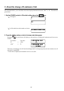
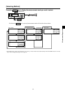
3. Selecting the Measurement Mode
The following measurement modes are available.
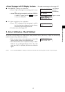
<Error Messages in LCD Display Section>
…
For other error messages, refer to page 107.
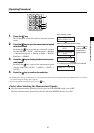
● “NO SYNC. SIGNAL” (when EXT mode is selected)
•
Cause 1 : The vertical synchronizing signal used for the display is not connected to the terminal on the
instrument.
Action : If EXT mode is selected, input the vertical synchronizing signal to the terminal on the instru-
ment properly.
•
Cause 2 :The frequency of the vertical synchronizing signal used for the display is below 40 Hz or beyond
200 Hz.
Action : Change SYNC mode to UNIV. mode and start measurement.
G Standard
R Standard