


27
Installation/Connection
When the optional 4-Probe Expansion Board CA-B04 is used
Guide
2. Installing the 4-Probe Expansion Board CA-B04
Installing the optional 4-Probe Expansion Board CA-B04 in the instrument allows simultaneous measurement of
the colors at up to 5 points on the display’s surface. Install the expansion board as shown below.
[Installation Method]
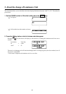
1. Remove the cover of the 4-Probe Expansion Board slot.
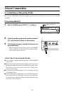
1 Set the POWER switch on the instrument to OFF.
2 Remove the two screws from the slot cover, and re-
move the cover.
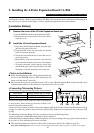
2. Install the 4-Probe Expansion Board.
1 Place the 4-Probe Expansion Board along the right-
and left-side guides in the slot.
2 Push the board all the way and make sure that the
board is connected properly.
3 Secure the board with the two screws that were re-
moved previously.
• Repeatability of the measurement value becomes
worse when the fixation by the screw is incomplete.
• To remove the board, remove the two screws first,
then hold the grip of the board and pull it out. After
the board is removed, attach the cover to the slot.
<Notes on Installation>
● When installing/removing the 4-Probe Expansion Board,
always set the POWER switch to OFF and pull the AC
power cord from the AC outlet first.
● Do not touch the connectors (gold plated parts) or ICs on the 4-Probe Expansion Board with your hands. If oil
or similar matter adheres to the connectors, wipe them with a soft, dry cloth.
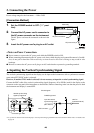
<Connecting Measuring Probes>
The following four types of measuring probes can be connected.
Probe model Product number and cord length
Measuring Probe CA-P02: 2 m/CA-P05: 5 m
High luminance Measuring Probe
CA-PH02: 2 m/CA-PH05: 5 m
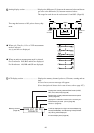
A total of five probes can be connected. When connecting two
or more probes, always make sure that one of them is con-
nected to the probe connector [P1].
Connect necessary number of probes to the probe connectors [P2] to [P5] on the 4-Probe Expansion Board. You do
not have to connect any probes to those connectors ([P2] to [P5]). Probes can be connected to any connectors ([P2]
to [P5]).
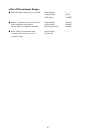
The Measuring Luminance Range will vary according to the type of Measuring Probe.
4 types of optionally available Measuring Probes can be connected.
As the Measuring Luminance Range of Measuring Probe will vary according to the type, please install one that is
fit for your use. Also, different types can be coresident.
● The connecting method for connectors [P2] to [P5] is the same as that for [P1]. (Refer to page 26.)
Notes when connecting probes: Probe connectors on the 4-Probe Expansion Board where no probe is connected must be capped.