119
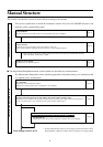
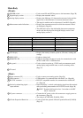
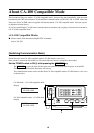
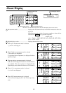
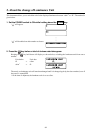
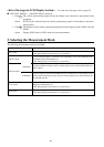
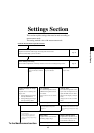
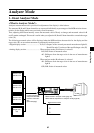
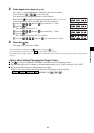
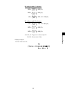
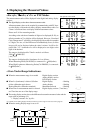
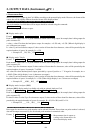
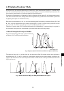
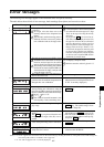
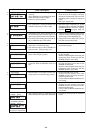
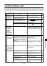
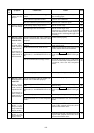
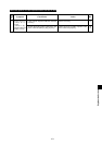
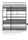
Explanation Section
2
8
5
3
4,91 6,7
2
9,11
4
3
5
6,10
1
7,8
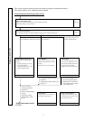
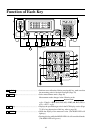
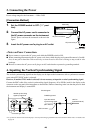
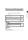
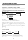
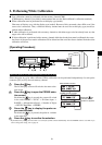
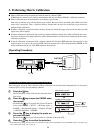
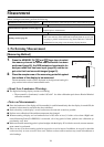
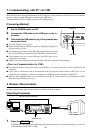
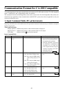
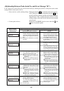
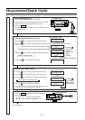
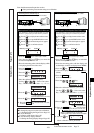
From the Measurement Preparation section
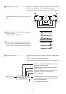
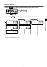
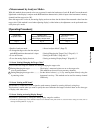
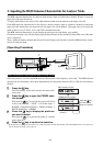
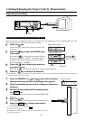
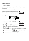
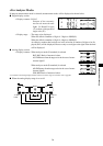
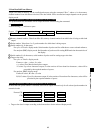
When performing measurement using user calibration
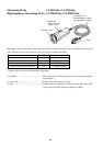
When the optional 4-Probe Expansion Board CA-B04 is used
User calibration is performed independently for probe
connectors ([P1] to [P5]) for each memory channel.
1
Press the key to display the menu selection screen.
2
Press the key to open the PROBE selection screen.
3
Press the key until the desired probe no. appears.
4
Press the key to confirm the selection.
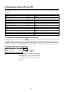
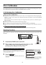
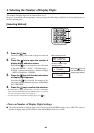
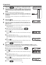
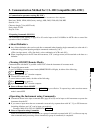
<User Calibration> Page 50
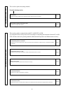
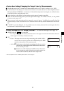
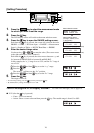
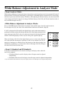
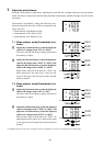
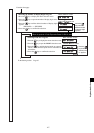
1.
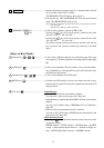
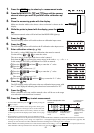
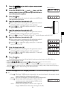
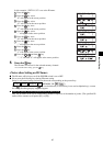
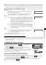
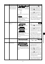
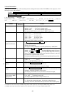
Performing White Calibration Page 51
Cannot be performed with memory channel CH00.
Memory channel Probe no.
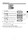
1.Press the MODE key to select xyLv mode.
2. Press the CH and keys to select the
desired memory channel.
3. Place the measuring probe with the display which
is displaying the known white color.
4. Press the HOLD key.
The HOLD LED will light up.
5. Press the key.
6. Press the key.
7. Enter the calibration values (x, y, Lv).
Ten-key ( to , )...
Used to enter values.
Key ...
The cursor moves in the order x → y → Lv → x.
8.Press the key.
9.Press the key.
10. Press the HOLD key. Measurement will start.
The HOLD LED will light off.
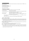
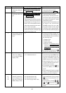
Setting Section Pages 45 to 74
Cursor
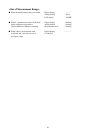
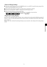
●To change the target color after user calibration:
*1 <Setting/Changing the Target Color> Page 118
●To set an ID name:
*2 <Setting an ID Name> Page 120
●To use the analog display function:
*3 <Setting the Analog Display Range> Page 120
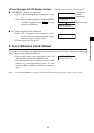
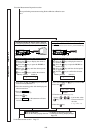
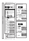
When the optional 4-Probe Expansion Board CA-B04 is used
User calibration is performed independently for probe
connectors ([P1] to [P5]) for each memory channel.
1
Press the key to display the menu selection screen.
2
Press the key to open the PROBE selection screen.
3
Press the key until the desired probe no. appears.
4
Press the key to confirm the selection.
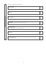
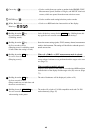
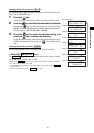
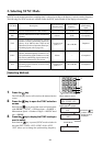
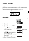
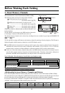
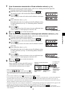
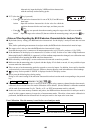
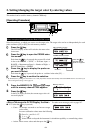
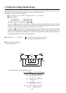
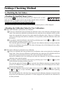
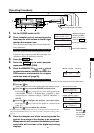
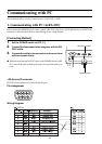
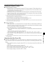
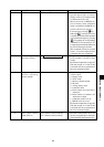
2.
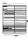
Performing Matrix Calibration Page 53
Cannot be performed with memory channel CH00.
1.Press the MODE key to select xyLv mode.
2. Press the CH and keys to select the
desired memory channel.
3. Place the measuring probe with the display and
set the display so that it can display known RGBW.
4. Press the key.
5. Cause the display to show red (green), (blue),
(white).
6. Press the HOLD key.
The HOLD LED will light up.
7. Press the ( , , ) key.
8.Enter the calibration values (x, y, Lv) for R.
Ten-key ( to , )...
Used to enter values
.
Key ...
The cursor moves in the order x → y → Lv → x.
9.Press the key.
10. Press the HOLD key.
The HOLD LED will light off. Measurement will start.
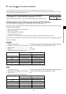
11.
Press the key.
Matrix calibration will be performed.
To the Measurement section Page 75
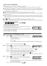
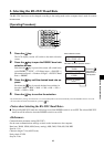
Memory channel Probe no.
“ * ” mark is displayed.
(
The mark will be displayed for W when the value is entered.
)
“ * ” mark is displayed.
(
The same mark will be displayed for G, B and W
when their values are entered.
)
Cursor
* Repeat steps 4 to 10 for G, B and W.
*
When “*” is displayed for R, G, B and W,
indicating that entry of all the values is complete,