


111111
Explanation Section
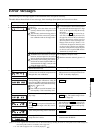
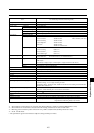
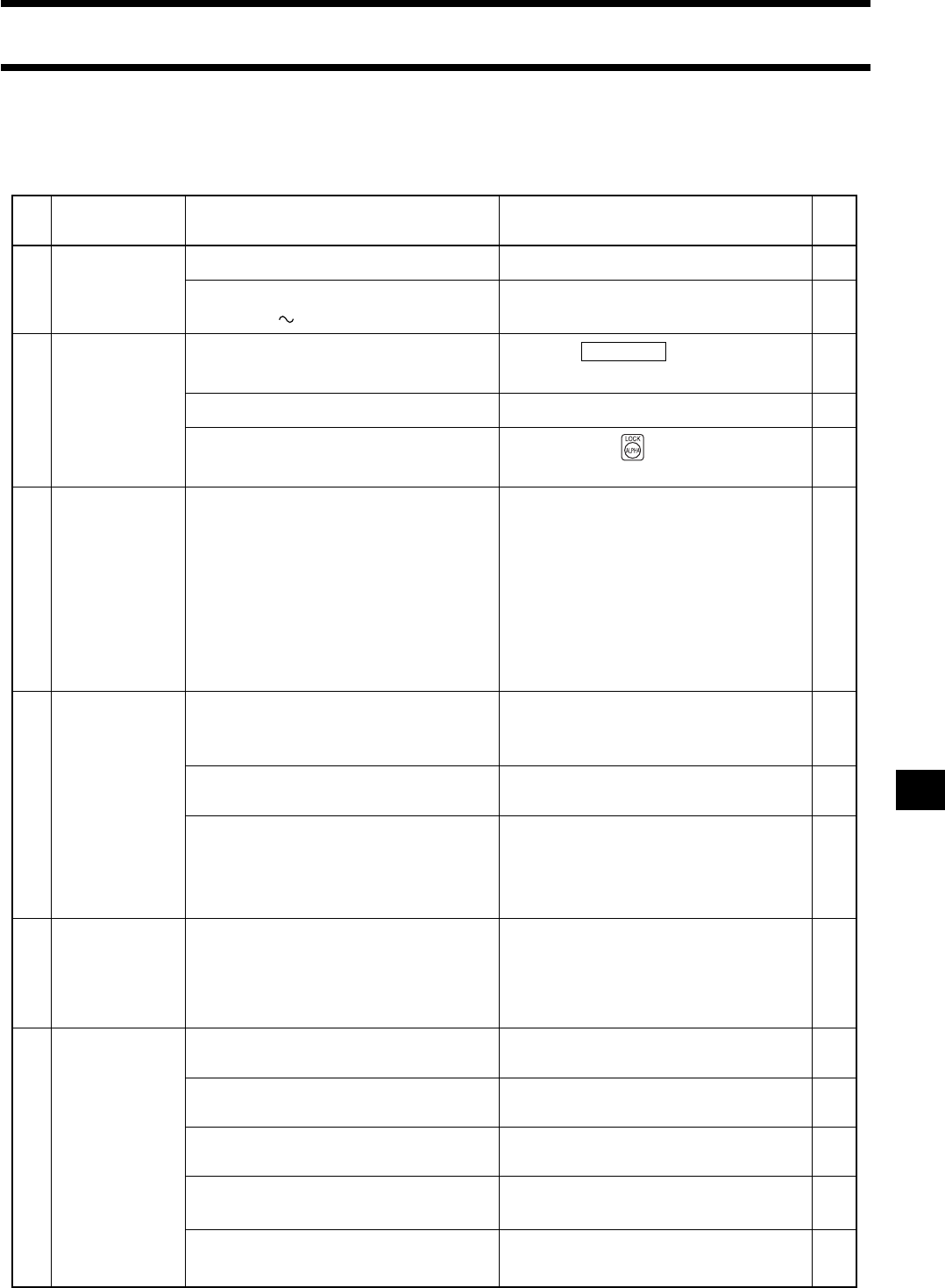
Troubleshooting Guide
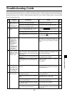
If any of the following symptoms occur with the instrument, take the corrective actions given in the table below. If
the instrument still does not operate correctly even if the necessary corrective actions are taken, the instrument
might have broken down. Contact a Konica Minolta authorized service facility. When doing so, please inform
them of the breakdown No.
Break-
down
No.
Action
Symptom
Check Point
Ref.
1
2
3
4
5
6
The display is
blank after the
POWER switch
is set to ON.
Is the AC power cord connected? Connect the AC power cord. 29
Is the power within the specified rating?
(100-240 V , 50-60 Hz, 50VA)
Use the power that is within the rating.
26
Check whether the instrument is in remote
mode (i.e. the REMOTE lamp is lit).
Press the REMOTE key to turn off re-
mote mode (i.e. the REMOTE lamp goes
out).
30
You are maybe pressing a key that does not function.
Press the correct key.
–
Check whether the key is in LOCK mode.
Hold down the key (for two seconds)
to cancel LOCK mode.
18
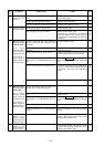
Is Lv of the calibration values for low lu-
minance?
If a low-luminance value is used as the cali-
bration value, this symptom may occur due
to calculation error.
50
Is an appropriate SYNC mode selected for
the display measured?
Select an appropriate SYNC mode and per-
form measurement.
38
You are maybe measuring a low-luminance
display.
Repeatability for x and y drops if a low-
luminance display is measured.
76
Keys are inoper-
able.
Turn the power OFF, turn it ON again, and
then perform zero calibration. If this symp-
tom still occurs, the instrument is broken
down.
29
35
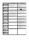
Zero calibration
does not end.
(“ZERO CALI-
BRATION” is
displayed in the
LCD display
section.)
“TOO BRIGHT”
is displayed even
if the light is
blocked properly.
Is the cable for the vertical synchronizing
signal connected to the terminal on the in-
strument and is the vertical synchronizing
signal input?
Connect the cable to the connector on the
instrument and display, and input the verti-
cal synchronizing signal.
28
“NO SYNC.
SIGNAL” is dis-
played in EXT
SYNC mode.
Does the level of the vertical synchroniz-
ing signal conform to the specified input
condition?
Set the signal level so that it conforms to
the specified input condition.
28
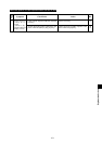
The calibration val-
ues entered for user
calibration using
keys differ from
those displayed at the
end of calibration.
Is the frequency of the vertical synchro-
nizing signal input to the instrument cor-
rect?
Make sure that the frequency is within the
following range.
40 to 200Hz
38
Measurement re-
sults fluctuate.
Is the measuring probe placed with the dis-
play and secured firmly?
Make sure that the probe is placed with the
display and secured firmly.
76
13
27
28
Is “4-Probe Expansion Board CA-B04”
fixed by the screw?
Fix it with the screw securely.
Is the AC power code connected to protec-
tive grounding terminal properly?
Be sure to connect the AC power cord's plug
to an AC outlet that has a protective ground-
ing terminal.