


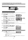

68
2. Setting the Analog Display Range
The analog display section displays the difference (%) between the measured value and the target color as well as
the difference (%) between measured values in the case of a measurement mode.
The range for each dot can be set as follows.
1 xyLv, T∆uvLv, u'v'Lv or XYZ measurement mode ..... ∆x, ∆y and ∆Lv
2 Analyzer Mode
For G-reference .............. R/G, B/G and ∆G
For R-reference............... ∆R, B/R and G/R
The range must be set independently of 1 and 2.
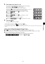
In the case of 1 , the range set here will be used commonly by all the modes. Thus, for instance, if ∆x and
∆y are set to 2% and ∆Lv is set to 10% for xyLv mode, ∆x and ∆y will be displayed in 2% and ∆Lv in 10%
irrespective of the measurement mode (xyLv, T∆uvLv, u'v'Lv or XYZ).
In the case of 2 , the value set for G (G-reference), the value set for R (R-reference), the values set for R/G
and B/G (G-reference) and those set for B/R and G/R (R-reference) will be common. Thus, for instance, if
∆G is set to 5% and both R/G and B/G are set to 3% in the case of G-reference, ∆R will be displayed in 5%
and both B/R and G/R in 3% in the case of R-reference.
● Settable range ........... 0.1 to 99%
–
In 0.1% step for the range from 0.1 to 9.9%
–
In 1% step for the range from 10 to 99%
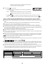
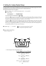
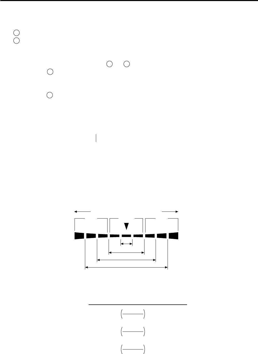
● How to Read Analog Display
When n% range is set
Below ±n%
Below ±n×2%
Below ±n×4%
Below ±n×8%
–+
Red Green Red
–n×8%
or lower
+n×8%
or higher
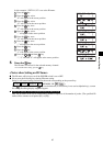
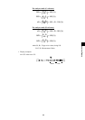
• Values displayed in the analog display section
For xyLv, T
∆∆
∆∆
∆uvLv, u'v'Lv or XYZ mode
∆x =
x
t
x–x
t
× 100 (%)
∆y =
y
t
y–y
t
× 100 (%)
∆Lv =
Lv
t
Lv–Lv
t
× 100 (%)
where, xt, yt, Lvt : Target color values
x, y, Lv : Measured values