62
1. Setting/Changing the Target Color by Measurement
[Operating Procedure]
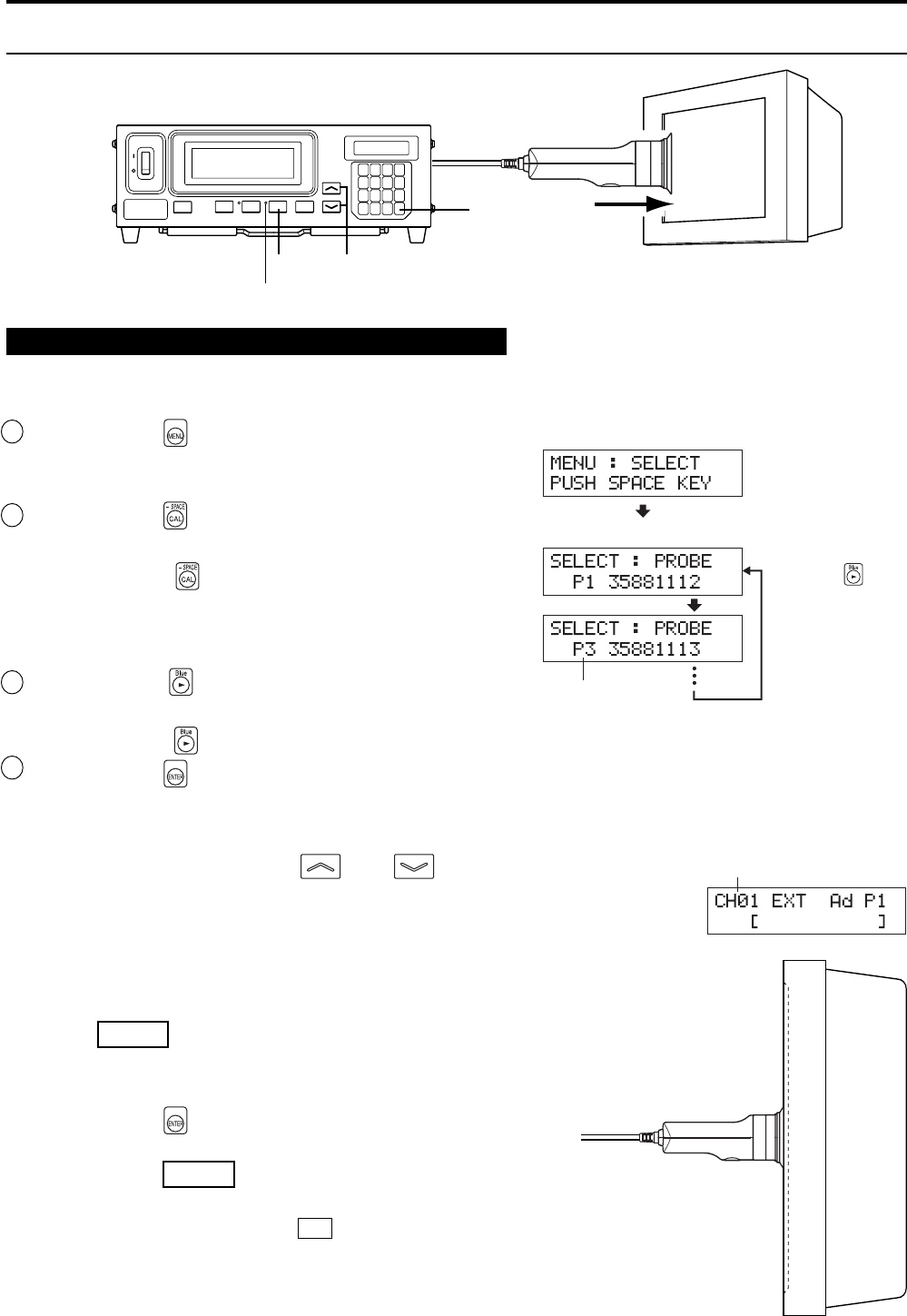
When the optional 4-Probe Expansion Board CA-B04 is used
Select the probe no. to which you want to set the target color. The target color can be set independently for each
probe connector ([P1] to [P5]) for each memory channel.
1 Press the key.
The LCD display section will switch to the menu selec-
tion screen.
2 Press the key to open the PROBE selec-
tion screen.
Each time the key is pressed, the screen will switch
in the order PROBE → SYNC → ID Name input →
RANGE → Measurement Speed → Number of Digits →
RS232C Baud Rate → PROBE.
3 Press the key to display the probe no.
you want to select.
Each time the key is pressed, the probe no. switches in the order [P1]
…
.
4Press the key to confirm the selection.
* By default (factory setting), the instrument is set so that [P1] will be selected automatically when the POWER switch is set to ON. If you
want to change this setting, refer to page 30.
1. Press the MEMORY CH and keys until the memory
channel where you want to set the target color appears.
2. Place the measuring probe with the display and take mea-
surement.
3. While the probe is placed with the display, press
the HOLD key.
The latest measured values will be hold and the HOLD LED
lights up.
4. Press the key.
The measured color of the display will be set as the target color.
5. Press the HOLD key to start measurement.
The HOLD LED will go out.
* To view the target color you set, press the MR key.
(For details, refer to page 72.)
* By default (factory setting), x=0.3127, y=0.3293 and Lv=40.00 (cd/cm
2
) are set
for each memory channel.
HOLD LED
2
1
4
3,5
Menu selection screen
PROBE selection screen
Probe no.
Press the
key
until the desired
probe no. appears.
Memory channel
