


IM 01E20C01-01E
10-2
10. MAINTENANCE
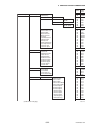
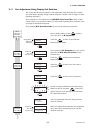
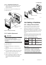
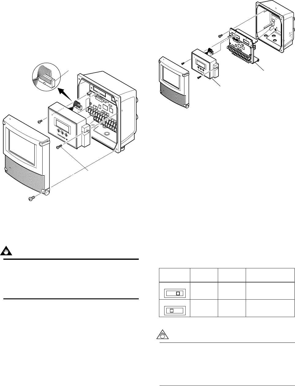
10.1.2.2 Assembling the Display Unit
(1) Align the display unit with the protrusion of the
connector facing forward and then make the
required connection.
(2) Secure the unit using its two mounting screws.
(3) Replace the cover.
Connector
Display unit mounting
screws (x 2)
F1002.EPS
Figure 10.1.2 Display Unit Assembly
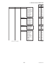
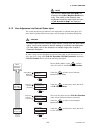
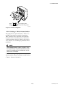
10.1.3 Amplifier Replacement
IMPORTANT
In case of amplifier replacement, it is necessary
to perform the parameter resetting.
For parameters, refer to Chapter 6: Parameter
Description.
(1) Turn off the power.
(2) Remove the cover.
(3) Remove all cables that are connected to the
terminals.
(4) Remove the display unit as described in Section
10.1.2.1.
(5) Loosen the amplifier assembly’s four screws while
supporting it with your hand (See Figure 10.1.3).
(6) Pull the amplifier assembly straight out.
(7) When reassembling the amplifier assembly, return
it to its original position and secure it in place
using the reverse procedure to that described
above.
F1003.EPS
Display unit assembly
Amplifier assembly
Figure 10.1.3 Amplifier Assembly
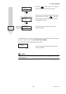
10.2 Setting of Switches
10.2.1 Setting of Burnout Switch
The burnout function sets the direction of current
output in situations where the CPU has become
damaged. Upon shipment from the manufacturing
plant, the burnout direction is set to High (i.e., 25 mA);
however, in cases where the optional code C1 has been
specified, the output direction will be set to Low (i.e.,
0 mA).
Modification of the burnout direction must be carried
out using the setting switch from the amplifier’s CPU
board (i.e. Switch 1) (See Figure 10.1.4).
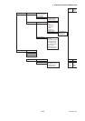
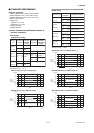
Table 10.1 Output Setting Pins for Burnout
T1001.EPS
Position
of Pin
Burnout
Direction
Output
Remarks
Low
High
Low High
Low
High
0 mA
25 mA
Set to Low for
optional code C1
Set to High before
shipment
NOTE
On the amplifier’s CPU board, the burnout
setting switch (i.e., Switch 1) and the write
protect switch (i.e., Switch 2) are located adja-
cent to each other. Accordingly, special care
should be taken when making switch settings.