


IM 01E20C01-01E
6-36
6. PARAMETER DESCRIPTION
6.5.2 Alarm Selection
The display and output differs depending on the alarm
levels. Certain types of alarm may or may not be
recognized as alarms, according to the settings of
certain parameters. The parameters that are relevant to
this function as follows.
[G20: Alm Out Act Mode] Setting of the active
mode for the alarm output
[G21: 4-20mA Alarm Out] Setting of the current
output during an alarm occurring.
[G30: Alm-Setting] Alarm recognition of “Setting
Alarm”
[G31: Alm-Sig Over] Alarm recognition of “Signal
Overflow Alarm”
[G32: Alm-Emp Pipe] Alarm recognition of “Empty
Pipe alarm”
[G33: Alm-HH/LL] Alarm recognition of “HH/LL
Alarm” (Refer to the descriptions of G12 and G13 for
more details regarding HH and LL alarms.)
[G34: Alm-Adhesion] Alarm recognition of “Adhe-
sion Alarm”
[G41: Alm Record1] Alarm record1
[G43: Alm Record2] Alarm record2
[G45: Alm Record3] Alarm record3
[G47: Alm Record4] Alarm record4
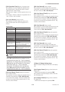
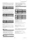
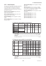
(1) Display and output condition for system alarms
Alarm description
Alarm
output
4-20 mA
output
Totali-
zation
Pulse Display unit
Alarm
record
Normal Normal
Normal Normal
Display Mode No
Closed
(On)
P Fault
EEPROM Fault
A/D(H) Fault
A/D(L) Fault
A/D(Z) Fault
Coil Open
EEPROM Dflt
Microprocessor(CPU)failure
EEPROM failure
A/D converter failure
Flowtube coil is open-circuit
EEPROM default values
Open
(Off)
Fixed
(G21 selection)
Stopped Stopped Recorded
Alarm Mode
(display of system
alarm message)
Open
(Off)
0mA or
25mA
Stopped Indetermination
10
11
12
13
14
15
16
T0648.EPS
Note: • Operations are performed in accordance with above table, when “Open (Off) Act” is set for G20: Alm
Out Act Mode.
• 4-20 mA output upon the occurrence of an alarm will be fixed at the value selected with G21: 4-20mA
Alarm Out.
*The output value is performed in accordance with the setting of the burnout switch. For information about
this switch, see Section 10.2.1.
Indeter-
mination
Indeter-
mination
(*)
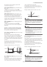
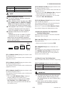
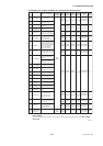
(2) Display and output condition for process alarms
Alarm
description
Selection
(parameter
number)
Alarm
output
4-20 mA
output
Tota li-
zation
Pulse
output
Display
unit
Alarm
record
30
31
32
33
Sig Overflow
Empty Pipe
HH/LL Alm
Adhesion Alm
Input signal error
Flowtube is not
filled with fluid
HH/LL Alarm
Electrode
adhesion alarm
T0649.EPS
Alarm Mode
(Message)
Alarm Mode
(Message)
Alarm Mode
(Message)
Alarm Mode
(Message)
Display Mode
Display Mode
Display Mode
Display Mode
Fixed
Continu-
ous (*)
Continu-
ous (*)
Continu-
ous (*)
Fixed
Stopped
Continu-
ous (*)
Continu-
ous (*)
Continu-
ous (*)
Stopped
Stopped
Continu-
ous (*)
Continu-
ous (*)
Continu-
ous (*)
Stopped
Normal
operation
Normal
operation
Normal
operation
Fixed Stopped Stopped
Recorded
No
Recorded
No
No
Recorded
No
Open
(Off)
Closed
(On)
Open
(Off)
Closed
(On)
Open
(Off)
Closed
(On)
Open
(Off)
Closed
(On)
YES
(G31)
NO
(G31)
YES
(G32)
NO
(G32)
YES
(G33)
NO
(G33)
YES
(G34)
NO
(G34)
Note: • Operations are performed in accordance with above table, when “Open (Off) Act” is set for G20: Alm
Out Act Mode.
• 4-20 mA output upon the occurrence of an alarm will be fixed at the value selected with G21: 4-20mA
Alarm Out.
*: Although outputs are continuous, output values are not guaranteed.