


IM 01E20C01-01E
4-5
4. WIRING
IMPORTANT
Do not wire the terminal without terminal sym-
bols in terminal layout labels.
4.4.3 Precautions for Wiring of Power
Supply Cables
When connecting to the power supply, observe the
points below. Failure to comply with these warnings
may result in an electric shock or damage to the
instrument.
WARNING
• Ensure that the power supply is OFF in order to
prevent electric shocks.
•Ensure the protective grounding terminal is
grounded before turning the power on.
• Use insulating sleeve crimp terminals (for 4-mm
screws) for the power supply wiring and protec-
tive grounding wiring.
• To prevent electric shocks, ensure the electrical
wiring cover (transparent) is attached.
• Install an external switch or circuit breaker as a
means to turn the powe off (capacitance; 15A,
conforming to IEC947-1 and IEC947-3). Locate
this switch either near the instrument or in other
places facilitating easy operation. Affix a
“Power Off Equipment” label to this external
switch or circuit breaker.
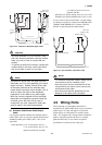
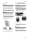
Wiring Procedure
1. Turn the instrument's power off, and remove the
wiring cover (transparent).
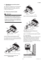
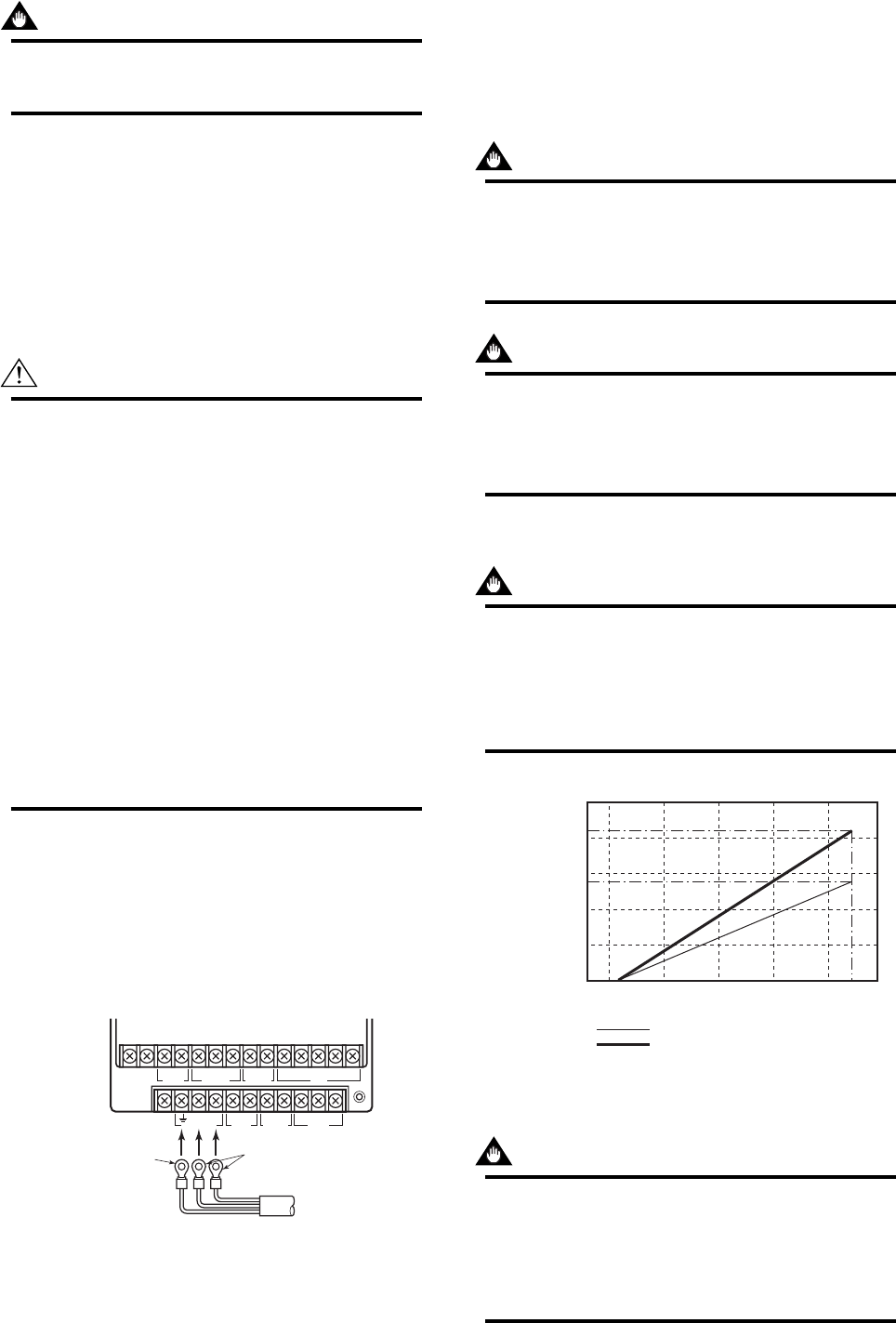
2. Wire the power supply cable and the functional
grounding cable to the power supply terminals.
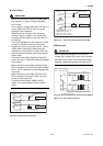
SBBASACAL–AL+COMSO2+SO1+I+ I–
CUR OUT STATUS OUT ALARM OUT SIGNAL
COMSI2+SI1+EX2EX1L/+N/–
POWER SUPPLY EXCITER
P–P+
PULSE OUT STATUS IN
Functional
grounding cable
Power supply cable
F0411.EPS
Figure 4.4.3 Electric Cable Wiring
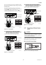
3. Reattach the electrical wiring cover (transparent).
4.4.4 DC Power Connection
When using DC power as the power supply for the
converter, give attention to the following points.
(1) Connecting Power Supply
IMPORTANT
Do not connect power supply with reversed
polarities.
L/+ terminal: connect +
N/
–
terminal: connect
–
IMPORTANT
Do not connect power supply with 100 to 240 V
AC or 100 to 120 V DC in the case of a 24 V
power supply version (power supply code 2).
It will give a damage to the converter.
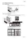
(2) Required Power Supply Voltages
IMPORTANT
When using a 24 V power supply, the specifica-
tion for the supply voltage is 24 V (–15% to
+20%), but the input voltage of the converter
drops due to cable resistance therefore it must
be used within the following ranges.
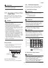
Supply Voltage and Cable Length
0
20.4 22 24 26 28.8
100 ( 330)
200 ( 660)
280 ( 920)
420 (1380)
F0411-2.EPS
Cable cross section area: 1.25 mm
2
Cable cross section area: 2 mm
2
Allowable cable length m(ft)
Usable range E (V)
(3) Setting Power Supply Frequency
IMPORTANT
Set the local commercial power frequency in
order to eliminate the effect of induction noise
from the commercial power supply.
Refer to “Chapter 6: Parameter Description” in
this manual. Parameter No. J30 and J31.