


IM 01E20C01-01E
8-2
8. OPERATION VIA HART COMMUNICATOR
8.1 Conditions of Communication Line
8.1.1 Interconnectwion between AXFA11 and HART Communicator
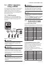
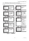
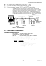
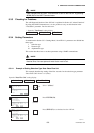
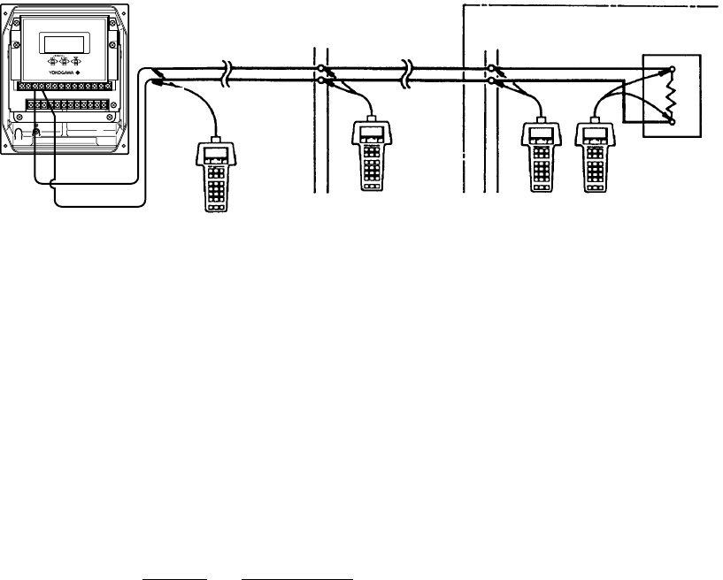
The HART Communicator can interface with the AXFA11 from the control room, the
AXFA11 site, or any other wiring termination point in the loop, provided there is a minimum
load resistance of 230 ⍀ between the connection and the receiving instrument. To communi-
cate, it must be connected in parallel with the AXFA11, and the connections must be non-
polarized. Figure 8.1.1 illustrates the wiring connections for a direct interface at the AXFA11
site. The HART Communicator can be used for remote access from any terminal strip as well.
AXFA11
+
–
4 to 20 mA DC signal line
Control room
Terminal board
Receiving instrument
load resistance:
230 Ω to 600 Ω
Relaying
terminals
HART
Communicator
Model 275
HART
Communicator
Model 275
HART
Communicator
Model 275
I + I -
F0802.EPS
Figure 8.1.1 Interconnection Diagram
8.1.2 Communication Line Requirements
Specifications for Communication Line:
Load resistance: 230 to 600 ⍀ (including cable resistance)
Minimum cable size: 24 AWG, (0.51 mm diameter)
Cable type: Single pair shielded or multiple pair with overall shield
Maximum twisted-pair length: 6,500 ft (2,000 m)
Maximum multiple twisted-pair length: 3,200 ft (1,000 m)
Use the following formula to determine cable length for a specific application:
L = –
65×10
6
(R×C)
(C
f
+10,000)
C
where: L = length in feet or meters
R = resistance in ohms, current sense resistance
C = cable capacitance in pF/ft or pF/m
C
f
= 50,000 pF