


IM 01E20C01-01E
6-10
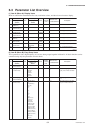
6. PARAMETER DESCRIPTION
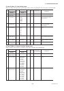
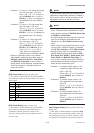
T0610-2.EPS
Item
Name
Display unit
(BRAIN)
Data range
Display unit
/BRAIN
Default value
(*): Indicated item
Units
R/W
Position
of decimal
point
Description
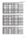
J30 Power Synch
(POWER SYNCH)
WNo
Yes
Yes Selects whether or not the internal
frequency is to be synchronized
with the power supply frequency.
J40 Memo 1
(MEMO 1)
W
ASCII 16 characters
Memo field
J41 Memo 2
(MEMO 2)
W
ASCII 16 characters
Memo field
J42 Memo 3
(MEMO 3)
W
ASCII 16 characters
Memo field
J50 Software Rev No
(SOFTWARE REV)
R— Software revision number
J60 —
(SELF CHECK)
RGood
Error
See “6.5 Alarm Functions”.
J31 Power Frequency
(POWER FREQ)
R/W Hz47.00 to 63.00 2 50.00
Displays the power-supply
frequency (for Power Synch =
“Yes”), or sets the power-supply
frequency (for Power Synch=“No”).
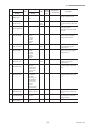
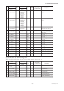
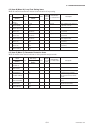
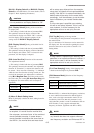
(10) Item K (Menu K): Diagnostic Function Setting items
Menu K contains items that are relevant to the diagnosis of insulation adhesion to the electrode.
T0611.EPS
Item
Name
Display unit
(BRAIN)
Data range
Display unit
/BRAIN
Default value
(*): Indicated item
Units
R/W
Position
of decimal
point
Description
K60 —
(SELF CHECK)
R Good
Error
See “6.5 Alarm Functions”.
K00 Diagnosis
(DIAGNOSIS)
K10 Adhesion Check
(ADHESION CHK)
WNo
Yes
No
Selects whether or not to perform diagnosis
of adhesion to the electrode.
K11 Adhesion Level1
(ADH LEVEL1)
WM ohm0.00 to 100.00 2 0.10
Sets the resistance value for adhesion
Level 1 to the electorode.
K12 Adhesion Level2
(ADH LEVEL2)
WM ohm0.00 to 100.00 2 0.50
Sets the resistance value for adhesion
Level 2 to the electorode.
K13 Adhesion Level3
(ADH LEVEL3)
WM ohm0.00 to 100.00 2 1.00
Sets the resistance value for adhesion
Level 3 to the electorode.
K14 Adhesion Level4
(ADH LEVEL4)
WM ohm0.00 to 100.00 2 3.00
Sets the resistance value for adhesion
Level 4 to the electorode.
K15
Adh Measure Value
(ADH MEAS VAL)
RM ohm—2
Displays the resistance value for
adhesion to the electrode.
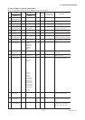
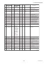
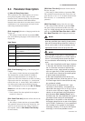
(11) Item M (Menu M): Automatic Zero-Adjustment Function Setting items
Menu M contains items that are relevant to automatic zero adjustment.
Item
Name
Display unit
(BRAIN)
Data range
Display unit
/BRAIN
Default value
(*): Indicated item
Units
R/W
Position
of decimal
point
Description
T0612.EPS
M60
—
(SELF CHECK)
R Good
Error
See “6.5 Alarm Functions”.
M11 Magflow Zero
(MAGFLOW ZERO)
M00 Adjustment
(ADJUSTMENT)
R/W -99.999 to 99.999 3 0.000
Displays the result of the automatic
zero adjustment, or sets the zero point.
M10 Auto Zero Exe
(AUTOZERO EXE)
W No Execution
Execution
No Execution Selects whether or not automatic
zero adjustment is carried out.
Linked with B50.