


IM 01E20C01-01E
11-1
11. OUTLINE
Cable Length for Specific Applications:
Use the following formula to determine the cable length
for specific applications:
Lϭ
65ϫ10
6
(RϫC)
Ϫ
(Cfϩ10,000)
C
where:
L=length in meters or feet
R=resistance in Ω (including barrier resistance)
C=cable capacitance in pF/m or pF/ft
Cf = maximum shunt capacitance of receiving devices
in pF/m or pF/ft
Note: HART is a registered trademark of the HART
Communication Foundation.
Data Security During Power Failure:
Data (parameters, totalizer value, etc.) storage by
EEPROM. No back-up battery required.
Indicator:
Full dot-matrix LCD (32ϫ132 pixels)
Lightning Protector:
The lightning protector is built into the excitation current
output, the current output, the signal common, and the
pulse/alarm/status input and output terminals. When
optional code A is selected, the lightning protector is built
into the power terminals.
Protection:
IP66, IP67, JIS C0920 immersion-proof type
Coating:
Case and Cover: Polyurethane corrosion-resistant
Coating Color: Silver gray (Munsell 3.2PB 7.4/1.2 or its
equivalent)
Cover Mounting Screws: Polyurethane corrosion-resistant
Coating Color: Mint green (Munsell 5.6BG 3.3/2.9 or its
equivalent)
Converter Material:
Case and Cover: Aluminum alloy
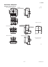
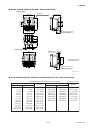
Mounting/Shapes:
• Mounting: 2-inch pipe, panel or surface mounting
• Electrical Connection: ANSI 1/2 NPT female
ISO M20 ϫ1.5 female
JIS G1/2 (PF1/2) female
• Terminal Connection: M4 size screw terminal
Grounding:
Grounding resistance 100 Ω or less
When optional code A is selected, grounding resistance
10 Ω or less shall be applied.
Combined Remote Flowtube:
• AXFA11 Converter can be combined with size 2.5 to 2600
mm (0.1 to 104 in.) of AXF Remote Flowtube.
However, the AXFA11 converter cannot combine with
AXF Remote Flowtube of TIIS flame proof type (In this
case, use the AXFA14 converter).
• If a combined converter is changed from AXFA11 to
AXFA14 or vice versa, a new meter factor must be
adjusted by flow calibrations.
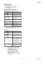
■ STANDARD SPECIFICATIONS
Excitation Method: (Combined with AXF Remote
Flowtube)
• Standard dual frequency excitation:
Size 2.5 to 400 mm (0.1 to 16 in.)
• Enhanced dual frequency excitation:
Size 25 to 200 mm (1.0 to 8.0 in.)
(Optional code HF1 or HF2)
• Pulsed DC excitation:
Size 500 to 2600 mm (20 to 104 in.)
Input Signal:
Two Status Inputs: Dry contact
Load resistance: 200 ⍀ or less (ON), 100 kΩ or more
(OFF)
Output Signals:
• One Current Output: 4 to 20 mA DC (load resistance: 1kΩ
maximum, including cable resistance)
• One Pulse Output:
Transistor contact output (open collector)
Contact capacity: 30 V DC (OFF), 200 mA (ON)
Output rate: 0.0001 to 10,000 pps (pulse/second)
• One Alarm Output:
Transistor contact output (open collector)
Contact capacity: 30 V DC (OFF), 200 mA (ON)
• Two Status Outputs:
Transistor contact output (open collector)
Contact capacity: 30 V DC (OFF), 200 mA (ON)
Communication Signals:
BRAIN or HART communication signal
(Superimposed on the 4 to 20 mA DC signal)
Distance from Power Line: 15 cm (6 in.) or more (Parallel
wiring should be avoided.)
BRAIN:
Communication Distance:
Up to 2 km (1.25 miles), when polyethylene insulated
PVC-sheathed cables (CEV cables) are used.
Communication distance varies depending on the type
of cable and wiring used.
Load Resistance:
250 to 600 Ω (including cable resistance)
Load Capacitance: 0.22 µF or less
Load Inductance: 3.3 mH or less
Input Impedance of Communicating Device:
10 kΩ or more (at 24 kHz)
HART:
Communication Distance:
Up to 1.5 km (0.9 mile), when using multiple twisted pair
cables. Communication distance varies depending on
the type of cable used.
Load Resistance:
230 to 600 Ω (including cable resistance)
11. OUTLINE