


IM 01E20C01-01E
4-4
4. WIRING
4.4 Wiring Connections
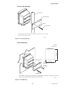
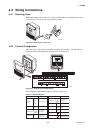
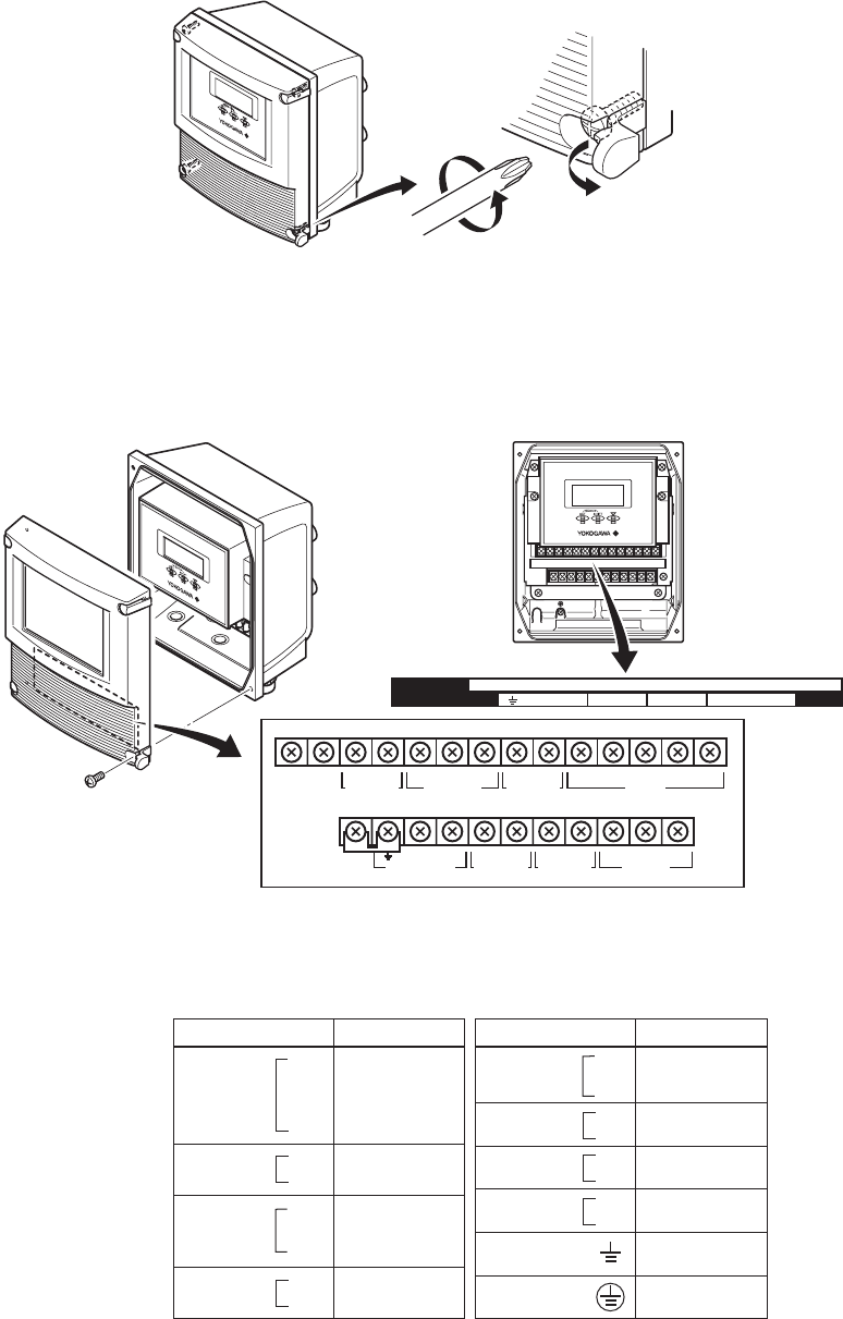
4.4.1 Removing Cover
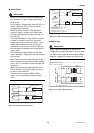
While supporting the front of the cover with your hand, flip the connecting screw protec-
tive cover over, and remove the four connecting screws.
F0409.EPS
Figure 4.4.1 Removing the Front Cover
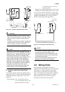
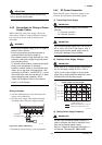
4.4.2 Terminal Configuration
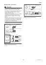
When the cover is removed, the connection terminals will be visible. The terminal con-
figuration labels are attached in the position shown in Figure 4.4.2.
F0410.EPS
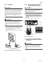
N/– L/+ EX2EX1 P– SI1+ SI2+ COMP+
I+ I– AL+ AL– C SA A B SBSO1+ COM
SO2+
I+ I–
CURRENT OUT
AL+ AL– C SA A B SB
ALARM OUT
N/– L/+
POWER SUPPLY
EX2EX1
EXCIT ATION
P– SI1+ SI2+ COMP+
PULSE OUT STATUS IN
SIGNAL
SO1+ COMSO2+
STATUS OUT
Figure 4.4.2 Terminal Layout Labels Position
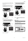
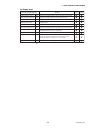
The description of the terminal symbols is shown in Table 4.4.1.
Table 4.4.1 Terminal Symbols
T0401.EPS
Terminal Symbols
Description
SIGNAL
CURRENT OUT
Flow signal input
Alarm output
Status output
(Two output)
Status input
(Two input)
Pulse output
Excitation current
output
Power supply
Functional grounding
Protective grounding
(Outside of the terminal)
Current output
4 to 20mA DC
ALARM OUT
STATUS OUT
Terminal Symbols
Description
STATUS IN
POWER SUPPLY
PULSE OUT
EXCITATION
SO1+
SO2+
COM
C
SA
A
B
SB
AL+
AL-
I+
I-
Sl1+
Sl2+
COM
P+
P-
EX1
EX2
L /+
N/-