


IM 01E20C01-01E
4-9
4. WIRING
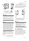
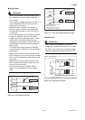
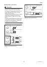
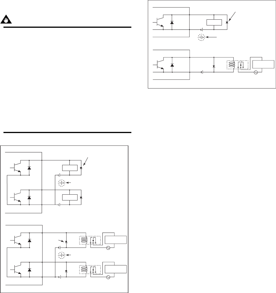
᭹ Status Output / Alarm Output
IMPORTANT
Since this is an isolated transistor output, be
careful of voltage and polarity when wiring.
Do not apply a voltage larger than 30V DC or a
current larger than 0.2A in order to prevent
damage to the instrument.
This output cannot switch an AC load. To switch
an AC load, an intermediate relay must be
inserted as shown in Figure 4.4.13 or Figure
4.4.14.
*The alarm output operates from closed (normal)
to open (alarm occurrence) in the default value
(as setup upon plant shipment). Changes can
be made via the parameter settings.
F0421.EPS
Load
Load
Protective diode
Protective
diode
External power supply
30V DC, 0.2A. max
AXFA11
External power supply
30V DC, 0.2A. max
AXFA11
This connection is not possible.
This connection is not possible.
SO1
+
SO2
+
COM
SO1
+
SO2
+
COM
Electromagnetic
valve
Electromagnetic
valve
AC power supply
Relay
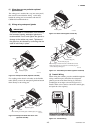
Figure 4.4.13 Status Output Connection
F0422.EPS
Load
Protective diode
External power supply
30V DC, 0.2A. max
AXFA11
AXFA11
This connection is not possible.
AL
+
AL
-
AL
+
AL
-
Electromagnetic
valve
AC power supply
Relay
Figure 4.4.14 Alarm Output Connection