


IM 01E20C01-01E
6-23
6. PARAMETER DESCRIPTION
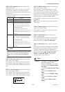
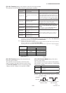
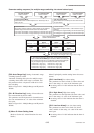
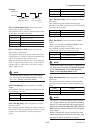
Parameter setting sequence
(for automatic multiple ranges switching)
F10: SO1 Function
Select a function
F11: SO2 Function
Select a function
F14: SO1/2 Active Mode
Select whether SO1 and SO2 output is to
be “Closed (On) Act” or “Open (Off) Act”
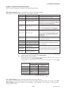
Function Selection
No Function: Output is stopped (*: other functions may be selected)
Fwd/Rev Ranges: Forward and reverse flow rate measurement
Auto 2 Ranges: Automatic 2-ranges switching
Auto 3 Ranges: Automatic 3-ranges switching
Auto 4 Ranges: Automatic 4-ranges switching
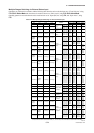
Refer to Table 6.4.1
and set F10 or F11.
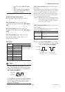
Set the spans for the ranges to be used.
No. 1 range Ϲ No. 2 range
Ϲ No. 3 range Ϲ No. 4 range
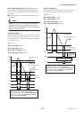
If “instantaneous flow rate % display (FR)” is selected for
Display Mode and A10: FLOW RATE(%) is selected for
BRAIN communication, the instantaneous flow rate %
and following symbols will be displayed only for multiple
ranges and forward/reverse flow measurement.
Forward No. 1 range : [F1] Reverse No. 1 range : [R1]
Forward No. 2 range : [F2] Reverse No. 2 range : [R2]
Forward No. 3 range : [F3]
Forward No. 4 range : [F4]
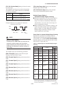
F30: Forward
Span 2
Forward No. 2 range
B23: Flow Span
Forward No. 1 range
F31: Forward
Span 3
Forward No. 3 range
F33: Reverse
Span 1
Reverse No. 1 range
F34: Reverse
Span 2
Reverse No. 2 range
F32: Forward
Span 4
Forward No. 4 range
F0607.EPS
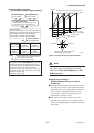
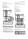
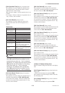
10% of No. 1 range
(set using F40)
10% of No. 2 range
(set using F40)
10% of No. 3 range
(set using F40)
Input
100%
No. 1 range
No. 2 range
No. 3 range
No. 4 range
Output
Reverse
Forward
Minimum span % within multiple and
forward/reverse (set using F41)
F0608.EPS
Figure 6.4.1 Multiple Ranges and Hysteresis Widths
NOTE
For more details regarding the setting of hyster-
esis width, refer to the description of setting
parameter for F40: Auto Range Hys and F41:
Bi Direction Hys.
Multiple Ranges Setting 2:
Multiple ranges switching via external
status input
For both the forward and reverse directions, switch-
ing of up to four ranges can be carried out based on
status input; however, switching between directions
is not possible. Switching between forward and
reverse ranges is carried out automatically only
when the flow direction reverses.
SI1 and SI2 status input terminals are used for
multiple range switching. For more details, refer to
Table 6.4.2: Multiple Ranges Switching via External
Status Input.