


IM 01E20C01-01E
4-7
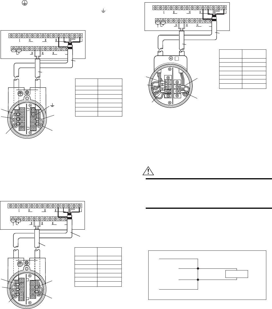
4. WIRING
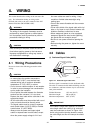
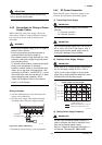
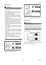
In case of explosion proof type for CENELEC ATEX,
FM, and CSA certification, connect wiring as shown in
the figure below.
In case of the explosion proof type, the protective
grounding of remote flowtube must be connected to
a suitable IS grounding system. In that case,
(functional grounding terminal) need not be connected.
I+ I–
CURRENT OUT
AL+ AL– C SA A B SB
ALARM OUT
N/– L/+
POWER SUPPLY
EX2EX1
EXCIT ATION
P– SI1+ SI2+ COMP+
PULSE OUT STATUS IN
SIGNAL
SO1+ COMSO2+
STATUS OUT
AXFA11 Converter
AXFC Dedicated signal
cable
Converter
Remote
flowtube
F0416.EPS
SA
A
B
SB
C
EX1
EX2
Taping*
A
B
Taping*
C
EX1
EX2
*Individually tape and insulate the
shields corresponding to SA and
SB on the remote flowtube side.
Excitation cable
EX2
EX1
A
B
C
Remote flowtube
Figure 4.4.6 Wiring Diagram
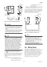
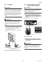
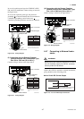
(3) Connection with the Remote Flowtube
(General-Purpose Use, Submersible Type,
Size 500 to 1000 mm (20 to 40 in.))
Connect wiring as shown in the figure below.
I+
4-20mA out
Shortbar
I–
CURRENT OUT
AL+ AL– C SA A B SB
ALARM OUT
N/– L/+
POWER SUPPLY
EX2EX1
EXCIT ATION
P– SI1+ SI2+ COMP+
PULSE OUT STATUS IN
SIGNAL
SO1+ COMSO2+
STATUS OUT
AXFA11 converter
Converter
Remote
flowtube
F040217.EPS
SA
A
B
SB
C
EX1
EX2
Taping*
A
B
Taping*
C
EX1
EX2
* Individually tape and insulate
the shields corresponding to SA
and SB on the remote flowtube
side.
Remote flowtube
EX2
Excitation
cable
EX1
A
B
C
AXFC dedicated
signal cable
Figure 4.4.7 Wiring Diagram
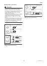
(4) Connection with the Remote Flowtube
(General-Purpose Use, Submersible Type,
Size 1100 to 2600 mm (44 to 104 in.))
Connect wiring as shown in the figure below.
I+
4-20mA out
I–
CURRENT OUT
AL+ AL– C SA A B SB
ALARM OUT
N/– L/+
POWER SUPPLY
EX2EX1
EXCIT ATION
P– SI1+ SI2+ COMP+
PULSE OUT STATUS IN
SIGNAL
SO1+ COMSO2+
STATUS OUT
Shortbar
F040218.EPS
AXFA11 converter
Converter
Remote
flowtube
SA
A
B
SB
C
EX1
EX2
Taping*
A
B
Taping*
C
EX1
EX2
* Individually tape and insulate
the shields corresponding to SA
and SB on the remote flowtube
side.
Remote flowtube
AXFC dedicated
signal cable
EX2
EX1
A
B
C
Excitation
cable
Figure 4.4.8 Wiring Diagram
4.4.7 Connecting to External Instru-
ments
WARNING
Before wiring with external instrument, be sure to
turn off the power supply for AXFA11 converter
and any external instruments.
Connect the AXFA11 terminal to external instruments,
giving attention to the following points.
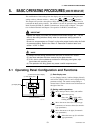
᭹ 4 to 20 mA DC Current Output
Resistive Load Max. 1 kΩ.
(When using BRAIN/ HART communication,
more than 250 Ω, less than 600 Ω).
Receiver
Instrument
AXFA11
l+
l-
F0417.EPS
Figure 4.4.9 4 to 20 mA DC Output Connection