


IM 01E20C01-01E
6-30
6. PARAMETER DESCRIPTION
This parameter selects the display content of the
second line for display unit.
[H12: Display Select3] Setting of the third line for
display unit
→ Refer to the description for parameter B42
This parameter selects the display content of the third
line for display unit.
[H20: Display Cycle] Setting of the display cycle
This parameter sets the cycle for the display-response
speed of display unit. Settings should be made in
accordance with the measurement environment by, for
example, setting a longer display cycle when using the
equipment in low temperatures.
[H30: Language] Selection of language used for the
display unit.
→ Refer to the description for parameter B10
This parameter can be used to select the language for
display unit.
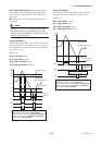
(8) Menu J: Auxiliary Function Setting items
Menu J contains setting items such as the flow direc-
tion, rate limits, and current output limits.
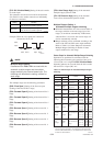
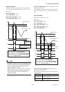
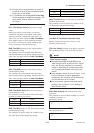
[J10: 4-20mA Low Cut] Setting of the low-cut range
for current output.
This parameter is used to force current output to
0%(i.e., 4mA) in the vicinity of 0% and setting for the
current (4 to 20mA) output low cut is made using a
percentage of the smallest flow rate span. However, the
low cut function will be terminated if this parameter is
set to 0%.
The indications of the instantaneous flow rates (%,
Actual instantaneous flow rate, mA, Bar graph) on the
display unit are the same action.
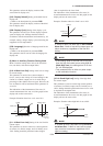
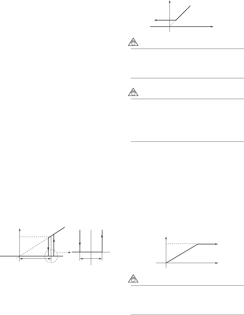
Example: Situation where low cut is set to 10%
F0615.EPS
Setting range: 0 to 10%
0.5% 0.5%
4mA
Output Setting value
Input
Hysteresis
fixed at 1%
5.6mA(10%)
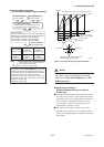
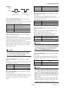
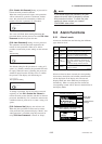
[J11: 4-20mA Low Lmt] Setting of the low limit for
current output
This parameter is used to restrict low current portions
of current (4 to 20mA) output, and it is initially set to
-20%. Setting should be performed when a higher
value is required for the lower limit.
The indications of the instantaneous flow rates (%,
Actual instantaneous flow rate, mA, Bar graph) on the
display unit are the same action.
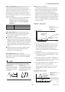
Example: Situation where low limit is set to 10%
F0655.EPS
4mA
Output
Input
5.6mA(10%)
NOTE
If “2.4mA or less” has been set for G21:4-20mA
Alarm Out, 2.4mA or less will be output upon an
alarm occurrence, regardless of the low limit
setting.
NOTE
• If the setting value for the low limit is not less
than the high limit value (as set using J12: 4-
20mA High Lmt), the setting alarm “4-20 Lmt
Err” will be displayed.
• This parameter has no effect on pulse output
or the totalization function.
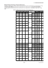
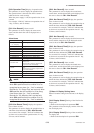
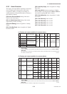
[J12: 4-20mA High Lmt] Setting of the high limit
for current output
This parameter is used to restrict high current portions
of current (4 to 20mA) output, and it is initially set to
120%. Setting should be performed when a lower value
is required for the higher limit.
The indications of the instantaneous flow rates (%,
Actual instantaneous flow rate, mA, Bar graph) on the
display unit are the same action.
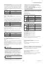
Example: Situation where high limit is set to 90%
F0656.EPS
4mA
Output
Input
18.4mA(90%)
NOTE
If “21.6mA or more” has been set for G21:4-20
mA Alarm Out, 21.6mA or more will be output
upon an alarm occurrence, regardless of the
high limit setting.