


IM 01E20C01-01E
8-21
8. OPERATION VIA HART COMMUNICATOR
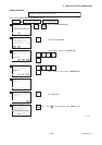
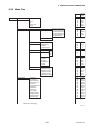
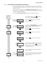
8.3.5 Menu Tree
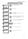
1 Device setup
1 Process Variables PV % rnge
PV
PV A0
Totl
Reverse Totl
Dif Totl
2 Diag/Service
1 Test/Status
1 Status
Status group 1(System alarms)
Status group 3(Process alarms)
Status group 5(Setting alarms)
Status group 6(Setting alarms)
Status group 7(Setting alarms)
Status group 8(Warnings)
2 Self test
1 Auto Zero Exe
2 Magflow Zero
3 D/A trim
4 Scaled D/A trim
2 Adjustment
3 Output Test
1 Loop test
4mA
20mA
Other
End
R
R
R
R
R
R
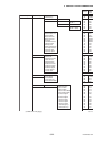
A10
A20
A21
A30
A31
A32
R
R
R
R
R
R
M10/B50
M11
–
–
W
W
W
W
–W
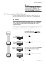
F0823-1.EPS
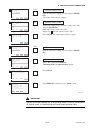
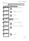
1 Adhesion Check
2 Adhesion Level1
3 Adhesion Level2
4 Adhesion Level3
5 Adhesion Level4
6
Adh Measure Value
4 Diagnosis
3 Easy Setup
1 Language
2 PV Damping
3 Base Flow Unit
4 Base Time Unit
5 PV Span
6 Flow Decimal Pnt
7 Total Unit
8 Total Scale
9 Pulse Unit
Pulse Scale
Display Select1
Display Select2
Display Select3
Auto Zero Exe
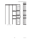
K10
K11
K12
K13
K14
K15
N10
N20
N21
N22
N23
N24
W
W
W
W
W
R
B10/H30
B20/C11
B21/C40
B22/C41
B23/C42
B24/C43
B30/D10
B31/D11
B32/E10
B33/E11
B40/H10
B41/H11
B42/H12
B50/M10
W
W
W
W
W
W
W
W
W
W
W
W
W
W
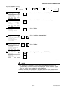
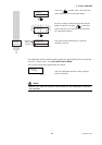
See
Section 6.5
“Alarm
Functions”
Parameter
of BRAIN
protocol
Read/Write
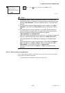
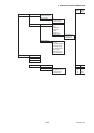
2 Test Mode
3 Test SO1
4 Test SO2
5 Test Alarm Out
6 Test SI1
7 Test SI2
W
W
W
W
R
R
(continued on next page)