


IM 01E20C01-01E
11-6
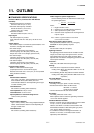
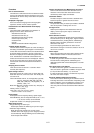
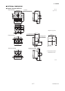
11. OUTLINE
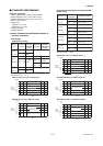
■ OPTIONAL SPECIFICATIONS FOR AXFA11 REMOTE CONVERTER
Item Specification Code
Burn Out Down
Lightning Protector
DC Noise Cut Circuit
A lightning protector is built into the power terminals.
In case of power supply code 2 (24 V AC/DC), this optional code is mandatory.
The output level is set to 0 mA during a CPU failure and is set 2.4 mA (-10%) or less during an alarm. Standard
products are delivered with a setting 25 mA during a CPU failure and 21.6 mA (110%) or more during an alarm.
The DC Noise Cut Circuit is built in. Available for 15 mm (0.5 in.) and larger sizes, and for fluids with the
conductivity of 50 µS/cm or higher. Nullifies the empty check and electrode adhesion diagnostics function.
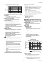
NAMUR NE43
Compliance
Output signal
limits: 3.8 to
20.5 mA
Failure alarm down-scale:
The output level is set to 0 mA during a CPU failure and is set
2.4 mA (–10%) or less during an alarm.
Failure alarm up-scale. The output level is set to 25 mA during a CPU failure and is set
21.6 mA (110%) or more during an alarm.
Active Pulse Output
Waterproof Glands
Active pulses are output in order to drive an external electromagnetic or electronic counter directly using
the converter’s internal power supply. (Nullfies the standard transistor contact pulse output.)
Output voltage: 24 V DC ±20%
Pulse specifications:
• The drive current of 30 to 150 mA
• Pulse rate: 0.0001 to 2 pps (pulse/second); Pulse width: 20, 33, 50, or 100 ms
Waterproof glands for G3/4 conduits or flexible tubes are attached to the electrical connections.
Available only for JIS G1/2 electric connections.
Waterproof glands are attached to the electrical connections. Available only for JIS G1/2 electric
connections.
Plastic Glands
Air Purge Fitting
Plastic glands are attached to the electrical connections. Available only for JIS G1/2 electric connections.
Provided with an air purge fitting (1.5 L/min air consumption) with purge air pressure at 0.14 MPa or
less. 1/4 NPT female (when electrical conn. code is 2 or 4) or Rc1/4 (PT 1/4) female (when electrical
conn. code is 0).
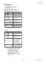
Stainless Steel Mounting
Bracket
Provided with a JIS SUS304 (AISI 304 SS/EN 1.4301 equivalent) stainless steel mounting bracket in
lieu of the standard carbon steel bracket.
AM11 Replacement Bracket
Provided with a special mounting bracket for replacing an AM11 converter with an AXFA11.
Calibration Certificate
Level 2: The Declaration and the Calibration Equipment List are issued.
Level 3: The Declaration and the Primary Standard List are issued.
Level 4: The Declaration and the Yokogawa Measuring Instruments Control System are issued.
Epoxy Resin Coating
Epoxy resin coating which has alkali-resistance instead of standard polyurethane resin coating. The
color is same as standard type.
High Anti-corrosion
Coating
Three-layer coating (polyurethane coating on two-layer epoxy resin coating) in the same range as
that for the standard coating. The color is same as standard type. Salt/alkali/acid/weather-
Painting Color Change
Coated in black (Munsell N1.5 or its equivalent.)
Coated in jade green (Munsell 7.5BG4/1.5 or its equivalent.)
Coated in metallic silver.
Stainless Steel Tag Plate Screwed JIS SUS304 (AISI 304 SS/EN 1.4301 equivalent) stainless steel tag plate. Choose this option
when an SS tag plate is required in addition to the standard nameplate with the tag number inscribed
on it.
Dimension (Height ϫ Width): Appr. 12.5 (4.92) ϫ 40 (15.7) mm (inch)
G3/4 Female
Waterproof Glands
Waterproof glands with union joints are attached to the electrical connections. Available only for JIS
G1/2 electric connections.
Waterproof Glands
with Union Joints
A
ELC
C1
C2
C3
EM
EW
EG
EU
EP
APC
SB
RK
SCT
P1
P2
P7
X1
X2
L2
L3
L4
T05.EPS
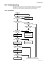
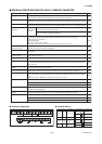
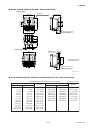
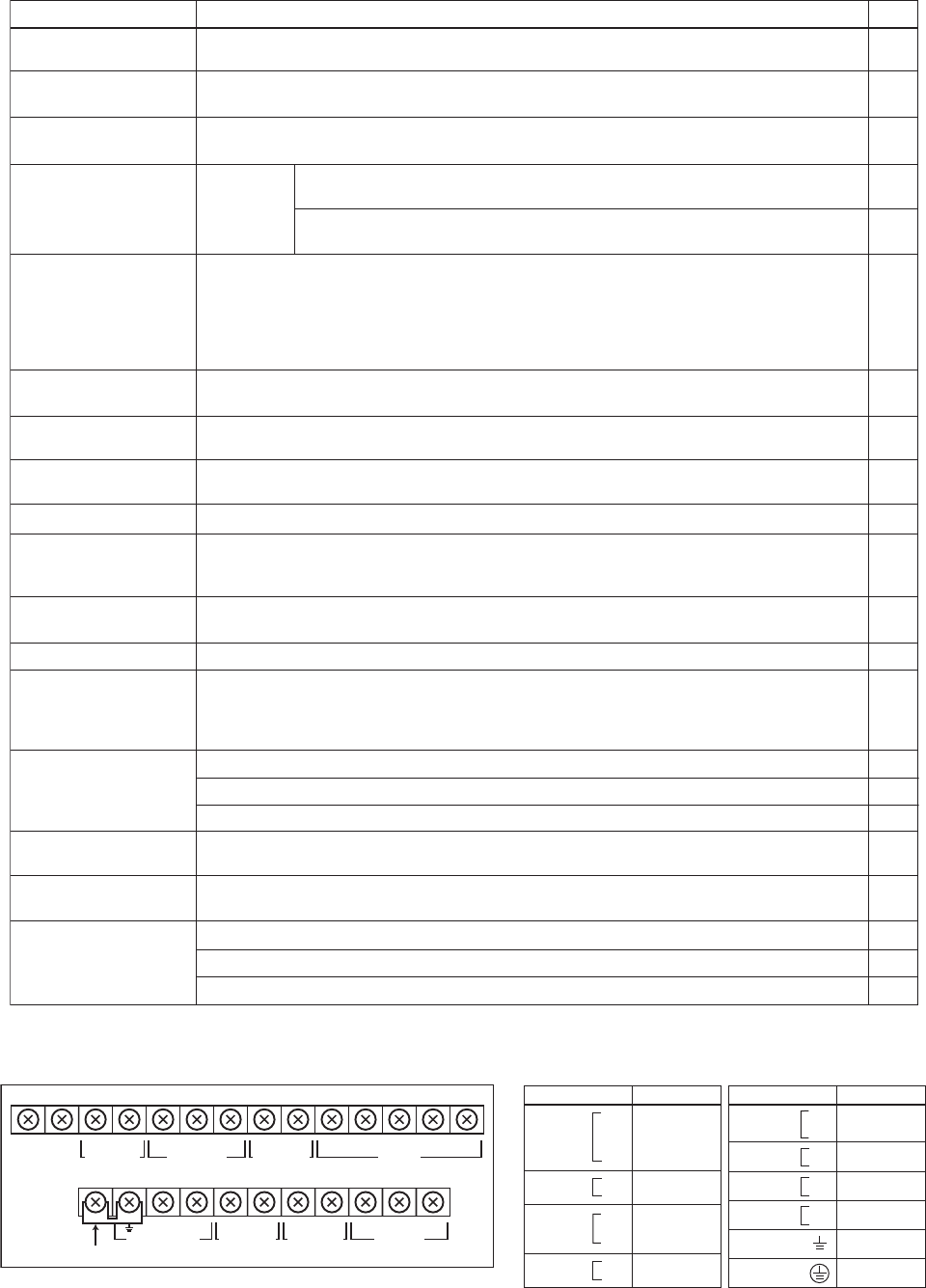
● Terminal Configuration
I+ I–
CURRENT OUT
AL+ AL– C SA A B SB
ALARM OUT
N/–
SHORT BAR
L/+
POWER SUPPLY
EX2EX1
EXCIT ATION
P– SI1+ SI2+ COMP+
PULSE OUT STATUS IN
SIGNAL
SO1+ COMSO2+
STATUS OUT
T06.EPS
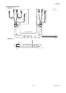
● Terminal Wiring
Terminal Symbols
Description
SIGNAL
CURRENT OUT
Flow signal input
Alarm output
Status output
(Two output)
Status input
(Two input)
Pulse output
Excitation current
output
Power supply
Functional
grounding
Protective grounding
(Outside of the terminal)
Current output
4 to 20mA DC
ALARM OUT
STATUS OUT
Terminal Symbols
Description
STATUS IN
POWER SUPPLY
PULSE OUT
EXCITATION
SO1+
SO2+
COM
C
SA
A
B
SB
AL+
AL-
I+
I-
Sl1+
Sl2+
COM
P+
P-
EX1
EX2
L /+
N/-
T07.EPS