


IM 01E20C01-01E
6-25
6. PARAMETER DESCRIPTION
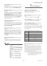
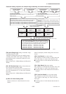
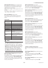
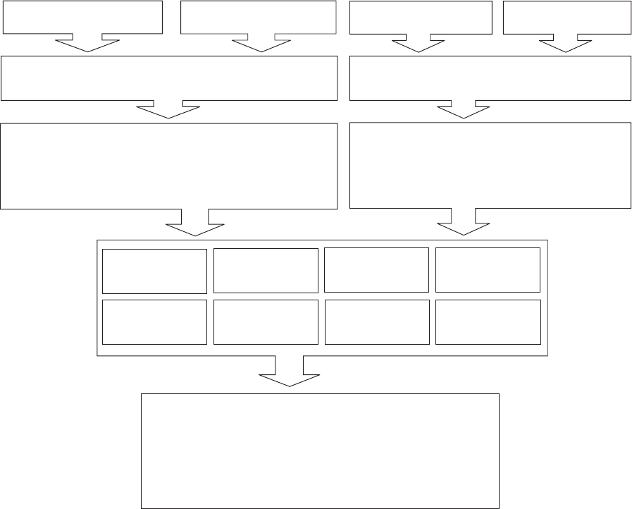
Parameter setting sequence (for multiple ranges switching via external status input)
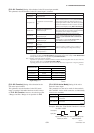
F10: SO1 Function
Select a function
F11: SO2 Function
Select a function
F14: SO1/2 Active Mode
Select whether SO1 and SO2 output is to be “Closed (on) Act” or
“Open (off) Act.”
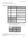
Function Selection
No Function: Output is stopped (*: other functions may be selected)
Fwd/Rev Ranges: Forward and reverse flow rate measurement
Ext 2 Answer: Answerback; 2-ranges switching via external status input
Ext 3 Answer: Answerback; 3-ranges switching via external status input
Ext 4 Answer: Answerback; 4-ranges switching via external status input
Function Selection
No Function: No input function (*: other functions may be
selected)
Ext 2 Ranges: 2-ranges switching via external status input
Ext 3 Ranges: 3-ranges switching via external status input
Ext 4 Ranges: 4-ranges switching via external status input
Refer to Table 6.4.2 and set F10
and F11 or F12 and F13.
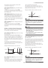
Set the spans for the ranges to be used.
No. 1 range Յ No. 2 range Յ No. 3 range Յ No. 4 range
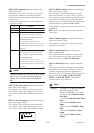
F12: SI1 Function
Select a function
F13: SI2 Function
Select a function
F15: SI1/2 Active Mode
Select whether SI1 and SI2 input is to be “Short Active”
or “Open Active.”
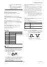
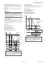
F33:Reverse
Span1
Reverse No. 1 range
B23:Flow Span
Forward No. 1 range
F0609.EPS
F34:Reverse
Span2
Reverse No. 2 range
F35:Reverse
Span3
Reverse No. 3 range
F36:Reverse
Span4
Reverse No. 4 range
F30:Forward
Span2
Forward No. 2 range
F31:Forward
Span3
Forward No. 3 range
F32:Forward
Span4
Forward No. 4 range
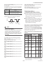
If “instantaneous flow rate % display (FR)” is selected for the Display
Mode and A10: FLOW RATE(%) is selected for BRAIN communication,
the instantaneous flow rate % and following symbols will be displayed
only for multiple ranges and forward/reverse flow measurement.
Forward No. 1 range : [F1]
Forward No. 2 range : [F2]
Forward No. 3 range : [F3]
Forward No. 4 range : [F4]
Reverse No. 1 range : [R1]
Reverse No. 2 range : [R2]
Reverse No. 3 range : [R3]
Reverse No. 4 range : [R4]
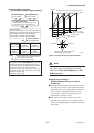
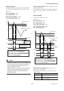
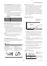
[F40: Auto Range Hys] Setting of automatic range-
switching hysteresis width
Automatic switching takes place for multiple ranges
switching when 100% of the range is exceeded, and
this parameter allows a hysteresis width to be set for
this switching.
Refer to Figure 6.4.1: Multiple Ranges and Hysteresis
Widths.
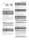
[F41: Bi Direction Hys] Setting of forward/reverse
flow measurement hysteresis width
This parameter sets the hysteresis for forward/reverse
flow rate measurement as a % value of the minimum
flow span.
Refer to Figure 6.4.1: Multiple Ranges and Hysteresis
Widths.
(6) Menu G: Alarm Setting items
(Refer to Section 6.5: Alarm Functions for more
details.)
Menu G principally contains setting items relevant to
alarms.
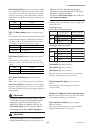
[G10: Low Alarm] Low alarm setting
This parameter sets the low limit (L) alarm value, and
this is done using a % value of the maximum span.
᭹ A setting value of -110% indicates that the alarm is
disabled.
[G11: High Alarm] High alarm setting
This parameter sets the high limit (H) alarm value, and
this is done using a % value of the maximum span.
᭹ A setting value of 110% indicates that the alarm is
disabled.
[G12: Low Low Alarm] Low-low alarm setting
This parameter sets the low-low limit (LL) alarm
value, and this is done using a % value of the maxi-
mum span.
᭹ A setting value of -110% indicates that the alarm is
disabled.