


IM 01E20C01-01E
4-2
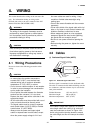
4. WIRING
20 (0.8)
10.5 (0.4)
AXFC
L (Specified Dimensions)
150
Ϯ5
8 (0.3) max.
150
Ϯ5
70 (2.76)
60 (2.36)
90 (3.54)
(5.9)
(5.9)
55 (2.17)
90 (3.54)
50 (1.97)
25 (0.98)
SA
SB
A
C
B
A
C
B
8(0.3) max.
White Black
Red
White Black Red
F0402.EPS
Unit : mm
(approx. inch)
On the
converter
side
On the
flowtube
side
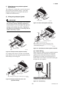
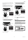
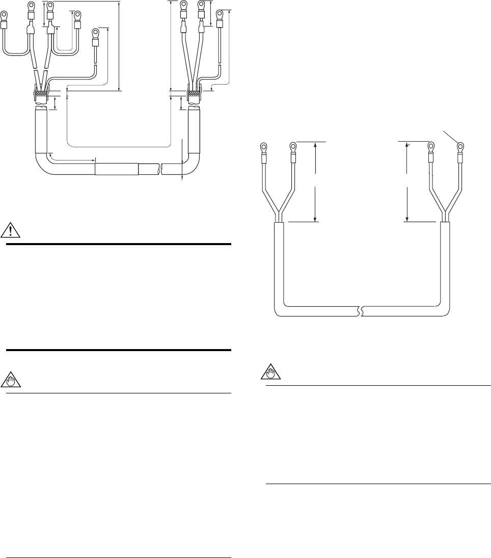
Figure 4.2.2 Treatment of Dedicated Signal Cables
CAUTION
• As crimp terminals A, B, SA, SB and C have
their own electrical potentials, securely insulate
them so as not to come in contact with one
another.
• To prevent a shield from coming in contact with
another shield or the case, cover each shield
with a vinyl tube or wrap it in vinyl tape.
NOTE
Conductors A and B carry the signal from the
electrodes, and C is at the potential of the liquid
(signal common). Shields SA and SB are kept
at the same potentials as the individual elec-
trodes (these are actively driven shields.) This is
done to reduce the effect of the distributed
capacitance of the cable at long cable length.
Note that, since the signals from the individual
electrodes are impedance converted inside the
converter, errors will result if they come in
contact with any other component. Great care
must be taken in the cable end treatment.
(2) Excitation Cable/Power Cable/Output
Cable
Use polyvinyl chloride insulated and sheathed control
cables (JIS C 3401) or polyvinyl chloride insulated and
sheathed portable power cables (JIS C 3312) or the
equivalent.
Outer Diameter: 6.5 to 12 mm (0.26 to 0.47 in.)
7.5 to 12 mm (0.30 to 0.47 in.) for
optional code EG, EU and EW
6 to 12mm (0.24 to 0.47 in.) for
optional code EP
Nominal Cross Section (Single wire): 0.5 to 2.5 mm
2
Nominal Cross Section (Stranded wire): 0.5 to 1.5 mm
2
In case of power cable, Green/Yellow covered conduc-
tor shall be used only for connection to PROTECTIVE
CONDUCTOR TERMINALS. Conform to IEC227,
IEC245 or equivalent national authorization.
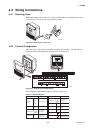
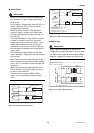
On the converter side
85 (3.35)
EX1
EX2
EX1
EX2
85 (3.35)
On the flowtube side
Unit : mm
(approx. inch)
F0403.EPS
Crimp Terminal
Figure 4.2.3 End Treatment of Excitation Cable
NOTE
• For excitation and power cables, always use a
crimp terminal with an insulation cover.
• Use crimp tools from the manufacturer of the
crimp terminal you want to use to connect the
crimp terminal and cable.
• Use crimp tools that are appropriate for the
diameter of the cable to be connected.
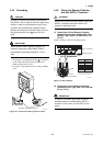
4.3 Wiring Ports
This instrument is of watertight construction as
stipulated in JIS C0920-1982 (Tests to prove protection
against ingress of water and degrees of protection
against ingress of solid objects for electrical equip-
ment.) It is shipped with a wiring bracket (waterproof
gland or waterproof gland with union) or a plastic
gland attached, only in cases where an optional
specification is selected for the wiring port.