IM 01E20C01-01E
6-18
6. PARAMETER DESCRIPTION
[D20: Total Execution] Operation setting for the
totalization function
This parameter sets “Start” and “Stop” of the totaliza-
tion function, in addition to performing the preset
function for the forward totalized value and the reverse
totalized value.
*: The preset function starts the count for totalization
from the set value.
Item Description
T0620.EPS
Start (initial value)
Stop
Preset Total
Preset Rev Total
Starts totalization
Stop totalization
Sets the preset value for totalization display that has
been specified as the forward totalized value. Preset
value are determined using D21: Ttl Set Val Lower
and D22: Ttl Set Val Upper.
In case that “Start” is sellected, the count for
totalization starts from the preset value. Setting of zero
as the preset value allows the zero-reset function to be
implemented.
Sets the preset value for totalization display that has
been specified as the reverse totalized value. Preset
value are determined using D21: Ttl Set Val Lower
and D22: Ttl Set Val Upper.
In case that “Start” is sellected, the count for
totalization starts from the preset value. Setting of zero
as the preset value allows the zero-reset function to be
implemented.
NOTE
Totalization presets can also be set up by using
status input. For details regarding the setting
method, refer to the descriptions of F12 and
F13.
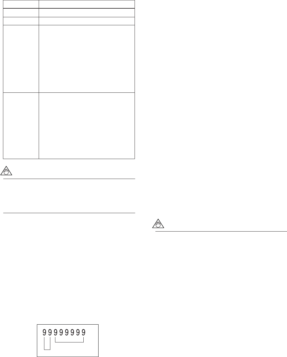
[D21: Ttl Set Val Lower] Setting of the totalization
preset value (lower 6 digits)
This parameter sets a totalization preset value in the
lower 6 digits of the 8-digit totalized value. If zero is
to be set as the preset value, “000000” should be set
here.
[D22: Ttl Set Val Upper] Setting of the totalization
preset value (upper 2 digits)
This parameter sets a totalization preset value in the
upper 2 digits of the 8-digit totalized value. If zero is
to be set as the preset value, “00” should be set here.
F0602.EPS
Upper 2 digits
Lower 6 digits
[D23: Ttl Switch Lower] Setting of the totalization
switch value (lower 6 digits)
The totalization switch function operates to set the
status output terminal (i.e., SO1 or SO2) to “Closed
(On)” when the forward internal totalized value reaches
or exceeds the totalization switch value. (For details
regarding the setting method for the status output, refer
to the descriptions of parameters F10 and F11.)
If this function is set up, the totalization count will stop
at 99999999.
D23 sets the lower 6 digits of the 8-digit totalization
switch value.
[D24: Ttl Switch Upper] Setting of the totalization
switch value (upper 2 digits)
This parameter sets the upper 2 digits of the 8-digit
totalization switch value.
[D30: Ttl User Select] Selection of the use of
special totalization unit
This parameter specifies whether or not special units
are used for totalized units. Actual setting of these
units is carried out using D31: Ttl User Unit.
[D31: Ttl User Unit] Setting of special totalization
units
Units of up to maximum 8 characters in length can be
specified using this parameter. The units set with this
parameter are displayed whenever totalization (i.e.,
FTL, RTL, DTL) is selected in the Display Mode, and
they are displayed for A30: TOTAL, A31: REV
TOTAL, and A32: DIF TOTAL when BRAIN
communication is being carried out.
NOTE
Example: To count in 1 dl (deci-liter) steps
with flow rate span=10 l/s.
Since 1 dl (deci-liter) = 0.1 l (liter),
“l (Liter)” is set for B21/C40: Base
Flow Unit,
“/s” is set for B22/C41: Base Time
Unit,
“10” is set for B23/C42: Flow
Span,
“Unit/P” is set for B30/D10: Total
Unit,
“0.1” is set for B31/D11: Total
Scale,
“Yes” is set for D30: Ttl User
Select,


