


IM 01E20C01-01E
6-6
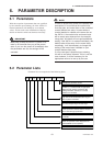
6. PARAMETER DESCRIPTION
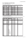
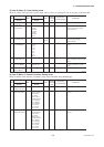
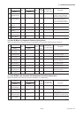
(5) Item E (Menu E): Pulse Setting items
Menu E contains items relevant to pulse output. This is used to set parameters such as the pulse scale and width.
T0606.EPS
Item
Name
Display unit
(BRAIN)
Data range
Display unit
/BRAIN
Default value
(*): Indicated item
Units
R/W
Position
of decimal
point
Description
E10 Pulse Unit
(PULSE UNIT)
Wn Unit/P
u Unit/P
m Unit/P
Unit/P
k Unit/P
M Unit/P
Pulse/s
Pulse/s (*) Selects the flow rate unit per one
pulse as used for pulse output.
Linked with B32.
E12 Pulse Width
(PULSE WIDTH)
W 50% Duty
0.05 ms
0.1 ms
0.5 ms
1 ms
20 ms
33 ms
50 ms
100 ms
50% Duty Selects the pulse width for pulse
output.
E11 Pulse Scale
(PULSE SCALE)
W0 to 32000 E10
(B32)
0 to 4 0 (*) Sets the flow rate per one pulse
as used for pulse output.
Linked with B33.
E13 Pulse Low Cut
(PULSE LOWCUT)
W0 to 100 % 0 3 % Sets the range in vicinity of 0%
within which pulse output will be
halted.
E20 Pulse Active Mode
(PLS ACT MODE)
W Closed(On)
Act
Open(Off) Act
Closed(On)
Act
Selects whether pulse output will
be set to “On Active” or “Off
Active.”
See “6.5 Alarm Function”.
E60 —
(SELF CHECK)
RGood
Error
E00 Pulse Set
(PULSE SET)
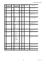
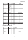
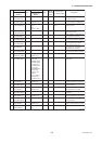
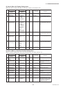
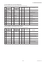
(6) Item F (Menu F): Status Functions Setting items
Menu F contains items relevant to multiplex range output and other status Input/Output.
T0607-1.EPS
Item
Name
Display unit
(BRAIN)
Data range
Display unit
/BRAIN
Default value
(*): Indicated item
Units
R/W
Position
of decimal
point
Description
F10 SO1 Function
(SO1 FUNCTION)
W No Function
Warning Output
Total Switch
H/L Alarm
HH/LL Alarm
Fwd/Rev Ranges
Auto 2 Ranges
Auto 3 Ranges
Auto 4 Ranges
Ext 2 Answer
Ext 3 Answer
Ext 4 Answer
No Function Selects function for the SO1
terminal
F10 SO2 Function
(SO2 FUNCTION)
W No Function
Warning Output
Total Switch
H/L Alarm
HH/LL Alarm
Fwd/Rev Ranges
Auto 2 Ranges
Auto 3 Ranges
Auto 4 Ranges
Ext 2 Answer
Ext 3 Answer
Ext 4 Answer
No Function Selects function for the SO2
terminal
F00 Status Function
(STATUS FUNC)