


IM 01E20C01-01E
4-6
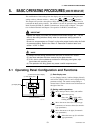
4. WIRING
4.4.5 Grounding
CAUTION
Be sure to connect the protective grounding of
the AXFA11 with a cable of 2mm
2
or larger cross
section in oder to avoid electrical shock to the
operators and maintenance engineers and to
prevent the influence of external noise. Connect
the grounding wire to the mark (100 ⍀ or
less).
IMPORTANT
When optional code A (lighting protector) is
selected, the ground should satisfy Class C
requirements (grounding resistance, 10 ⍀ or
less).
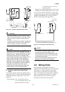
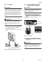
• The protective grounding terminals are located
on the inside and outside of the terminal area.
Either terminal may be used.
• Use 600 V vinyl insulation wires as the grounding
wires.
F0414.EPS
Protective grounding terminals
Figure 4.4.4 Protective Grounding Terminal Location
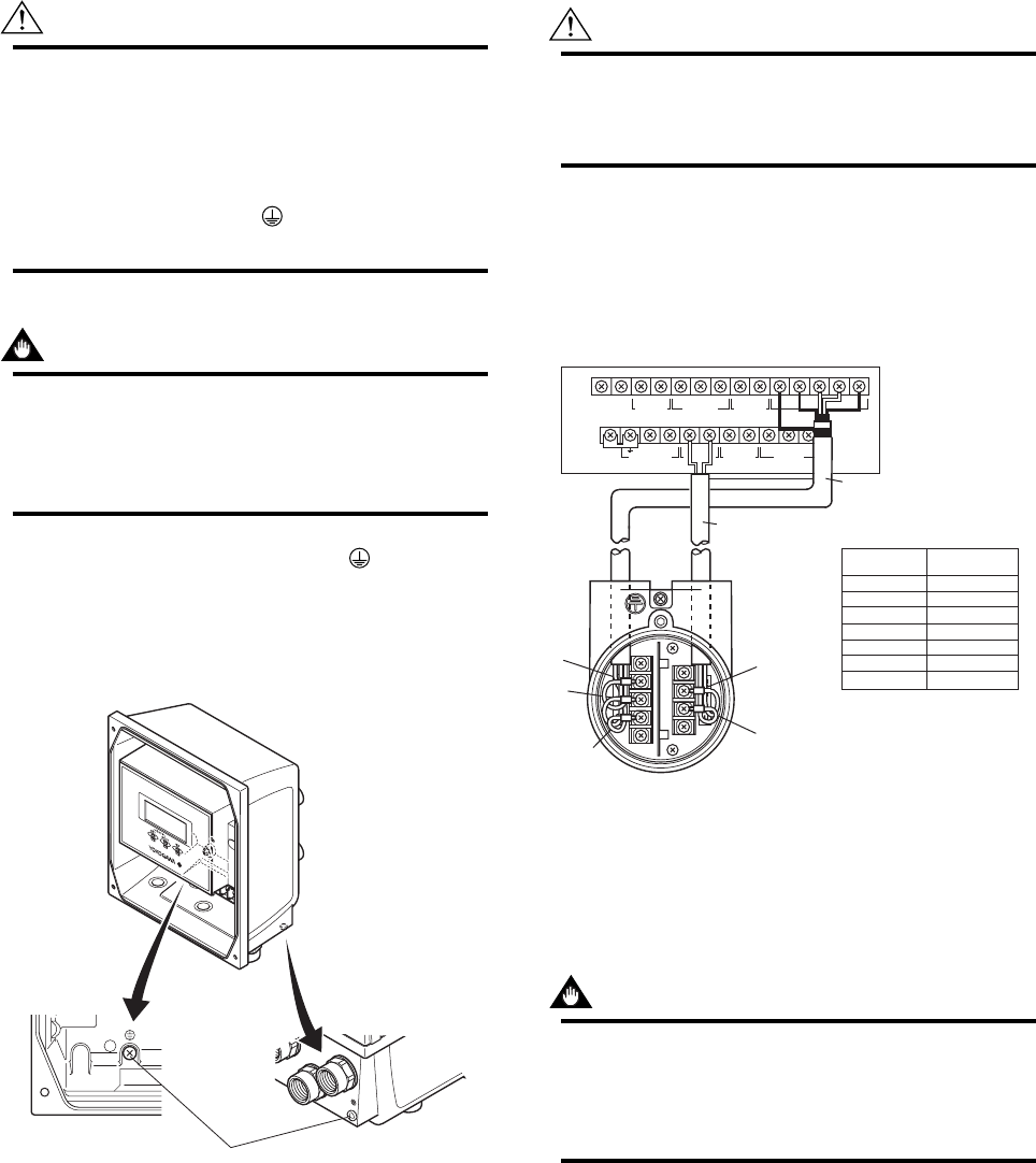
4.4.6 Wiring the Remote Flowtube
with the AXFA11 Converter
WARNING
Before wiring, be sure that the power supply for
AXFA11 converter has been turned off to
prevent an electrical shock.
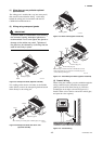
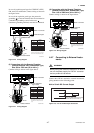
(1) Connection with the Remote Flowtube
(General-Purpose Use, Submersible Type,
Sanitary Type, Size 2.5 to 400 mm (0.1 to
16 in.))
Connect wiring as shown in the figure below.
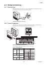
I+ I–
CURRENT OUT
AL+ AL– C SA A B SB
ALARM OUT
N/– L/+
POWER SUPPLY
EX2EX1
EXCIT ATION
P– SI1+ SI2+ COMP+
PULSE OUT STATUS IN
SIGNAL
SO1+ COMSO2+
STATUS O UT
AXFA11 Converter
Remote flowtube
AXFC Dedicated signal
cable
Converter
Remote
flowtube
F0415.EPS
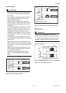
SA
A
B
SB
C
EX1
EX2
Taping*
A
B
Taping*
C
EX1
EX2
* Individually tape and insulate the
shields corresponding to SA and
SB on the remote flowtube side.
EX2
EX1
A
B
C
Excitation cable
Figure 4.4.5 Wiring Diagram
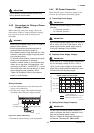
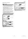
(2) Connection with the Remote Flowtube
(Explosion proof Type, Size 2.5 to 400 mm
(0.1 to 16 in.))
IMPORTANT
In case of TIIS Flame proof type, a remote
flowtube cannot be combined with AXFA11
converter. In this case, use the AXFA14 con-
verter.