146
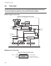
CHAPTER 6 FG Input
■ Operation of Capstan Input
●
Operation of Multiplying circuit
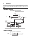
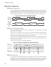
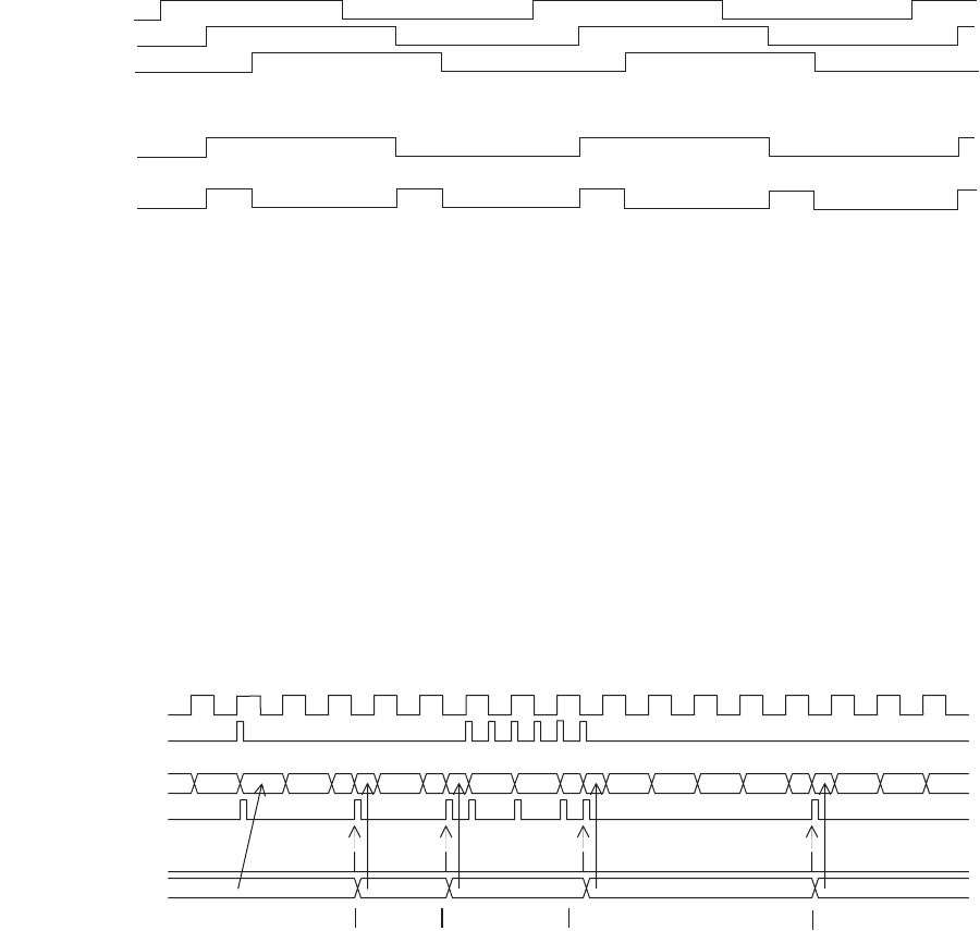
The capstan FG (CFG) input is input to the 8-bit programmable divider via "Slew" or double circuit by
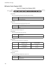
setting the multiplication select (DUB) bit of the capstan control register (CAPC). The input CFG signal is
edge detected after division that was set by the capstan control register (CAPDVC) is performed, and then
passes through the capstan mask timer, and is connected to the FRC capture unit as the DVCFG signal.
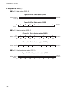
Figure 6.2-6 CFG output by multiplication selection
●
Operation of 8-bit Programmable divider
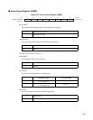
The programmable divider can be divided within the range between 1 to 255 by the value set to the capstan
input control register (CAPDVC).
When the value set to CAPDVC is "00
H
", division is not executed, and both edges of the CFG input are
directly output as the DVCFG signal. When values other than "00
H
" are set to CAPDVC, the output
divided by the rising edge of the CFG input is output as the DVCFG signal.
When the value set to CAPDVC is updated during division, the counter value is updated immediately after
the update. In this case, the DVCFG output is masked if the counter is updated simultaneously with the
DVCFG output (reload operation).
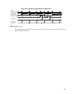
Figure 6.2-7 shows the sequence of the programmable divider.
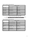
Figure 6.2-7 Operation timing diagram of programmable divider
●
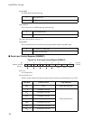
Operation of Mask Timer
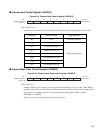
The mask timer loads the CAPMTC value and starts counting, and also masks the DVCFG output after
detecting the CFG division output edge. When the DVCFG output is detected during the masking period,
the CFGD flag is set. Even if the CAPMTC value is updated during the masking period, load operation to
the mask timer will not be executed. This updated value will be valid from the next masking period.
Input CFG
Delay CFG1
Delay CFG2
CFG output
Through
(DUB=0)
2 multiplication
(DUB=1)
CFG input
DVCFG output
Counter value
Reload timing
Write timing
CAPDVC value
3
3 0 8 5
2 1 3 2 1 3 2 1 0 0 0 0 8 7 6 5 4 3 5 4 3 2


