183
9.3 Operation of Real Timing Generator (RTG)
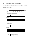
Initiation procedure of the real timing generator (RTG) and RTG output timing are
described.
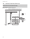
■ Initiation Procedure of Real Timing Generator (RTG)
1. Performs the initialization of control register.
2. Set the output data to RTGxD. In this case, do not use the command with RMW.
3. Set the output time to RTGxTH, L. In this case, the output data set by 2) is transferred to FIFO and EMP
flag becomes 0. 3 machine cycles are required for the EMP flag to be determined after setting the output
time. So if the flag is to be checked immediately after setting the output time, test should be carried out
after executing dummy read, etc.
Notes:
• Do not use word access commands to set the output data and output time.
• Use half-word access commands to set the output time.
• Prior to setting up the output time, set up the output data.
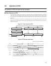
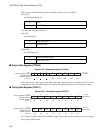
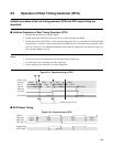
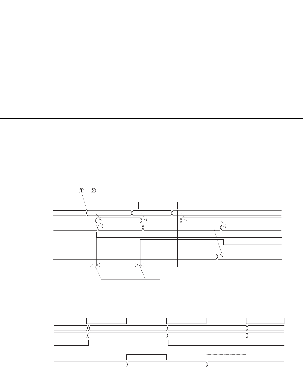
Figure 9.3-1 Operation timing of FIFO
■ RTG Output Timing
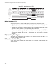
Figure 9.3-2 Output timing of RTG
RTGxT write
Out Data
Fifo 1st
Fifo 2nd
EMP flag
FUL flag
RTG Output
3 Machine cycle (3 x φ)
XXXX T0001
T0001
T0001
T0002
T0002
T0001
T0003
T0003
T0003
T0001XXXX
XXXX
XXXX
FRC2/3
FRC value
CMP latch
FRC. EQ. TD
Output timing
RTG Output
FFFF
0000 0000
0000 0003
nnnn
0003
nnnn
OUT
(
T0
)


