


78
CHAPTER 3 CPU
LDI:8 #00110000b,R1 ; CCK=00, PCK=00, CHC=0
STB R1,@R2 ; CPU clock=f, Peripheral clock=f, f=direct
LDI:8 #10110000b,R1 ; CCK=10, PCK=00, CHC=0
STB R1,@R2 ; CPU clock=1/4f, Peripheral clock=f, f=direct
Setting "1" to the CHC bit of the gear control register selects the 1/2 division circuit output as the source
clock, and uses "0" and the clock whose cycle is the same as the clock from the oscillation circuit as they
are. The CPU system and peripheral system are simultaneously changed to switch the source clock.
[example]
LDI:8 #01110001b,R1 ; CCK=01, PCK=00, CHC=1
LDI:32 #GCR,R2
STB R1,@R2 ; CPU clock=1/2f, Peripheral clock=f, f=1/2xtal
LDI:8 #00110001b,R1 ; CCK=00, PCK=00, CHC=1
STB R1,@R2 ; CPU clock=f, Peripheral clock=f, f=1/2xtal
LDI:8 #00110000b,R1 ; CCK=00, PCK=00, CHC=0
STB R1,@R2 ; CPU clock=f, Peripheral clock=f, f=direct
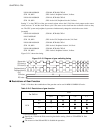
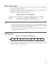
Figure 3.12-13 shows the timing.
Figure 3.12-13 Diagram of gear switching timing
■ Restrictions of Gear Function
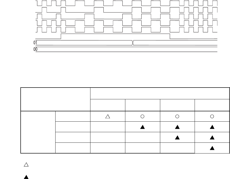
Table 3.12-6 shows the combination of the gear that can be used in MB91191/MB91192 series.
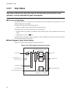
Source clock
CPU clock (a)
CPU clock (b)
Peripheral clock (a)
Peripheral clock (b)
CHC
CCK value
0 0
PCK value
Table 3.12-6 Restrictions of gear function
For CHC=0
CCK
0, 0 0, 1 1, 0 1, 1
PCK
0, 0
0, 1 ×
1, 0 × ×
1, 1 × × ×
×: Selection disabled
: Specify the 1 Wait in the Wait control register before setting. (Refer to "CHAPTER 20 Wait
Controller")
: The resource of the SIO and PPG is disabled the operation.