


56
CHAPTER 3 CPU
3.11 Memory Access Mode
In the FR20 series, operation mode is controlled by the mode pins (MD2, 1, 0) and the
mode register (MODR).
■ Operation Mode
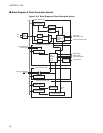
In the operation mode, there are a bus mode and an access mode.
●
Bus Mode
The bus mode controls the internal ROM operation and external access function operation, and is specified
by the mode set up pins (MD2, 1, 0) and M1, M0 bit of the mode register (MODR).
●
Access mode
The access mode controls the external data bus width, and is specified by the mode set up pins (MD2, 1, 0)
and BW1, 0 bits within the AMD0/AMD1/AMD32/AMD4 and AMD5 (address mode registers).
■ Mode Pin
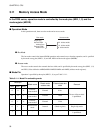
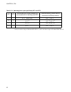
Operation is specified by three pins (MD2, 1, 0) as per Table 3.11-1 .
Single-chip
Internal ROM
external bus
32 - bit bus widht
16 - bit bus widht
External ROM
external bus
8 - bit bus widht
Bus mode Access mode
Table 3.11-1 Mode Pin and setting mode
Mode pin
Mode name
Reset vector
access area
External data bus
width
Remark
MD2 MD1 MD0
0 0 0
External
vector mode 0
External 8 bits
The use of the terminal
is prohibited.
0 0 1
External
vector mode 1
External 16 bit
0 1 0
External
vector mode 2
External 32 bit
0 1 1
Internal vector
mode
Internal (Mode register) Single-chip mode
1 - - - - -
The use of the terminal
is prohibited.