


63
3.12.2 Standby Control Register (STCR)
This register controls standby operations and specifies the oscillation stabilization wait
time.
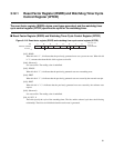
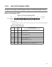
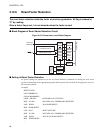
■ Standby Control Register (STCR)
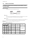
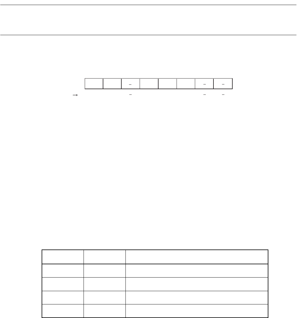
Figure 3.12-4 Standby control register (STCR)
[bit7]:STOP
When "1" is written to this bit, the status will be stop that stops the internal peripheral clock, the internal
CPU clock, and oscillation.
[bit6]:SLEP
When "1" is written to this bit, the status will be standby that stops the internal CPU clock. If "1" is
written to both the STOP bit and this bit, the STOP bit is handled as the priority, so the status will be
stop.
[bit5]:(Reserved)
[bit4]:SRST
When "0" is written to this bit, a software reset request is generated.
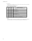
[bit3, 2]:OSC1, 0
These bits specify the oscillation stabilization wait time. These bits and selected cycle have the
following relationship. This bit is initialized by a power-on reset, and is unaffected by any other reset
factors.
Note: φ is twice as large as X0 when GCR CHC is 1, and is one time as large as X0 when GCR CHC is 0.
[bit1, 0]:(Reserved)
There are reserved bits. The reading value is undefined.
7 6 5 4 3 2 1 0
Initial value
000111--
B
bit
R/W R/W R/W R/W R/W
Access
Address: 00000481
H
STOP SLEEP SRST OSC1 OSC0
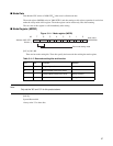
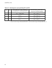
Table 3.12-2 Oscillation stabilization wait time specified by OSC1 and OSC0
OSC1 OSC0 Oscillation Stabilization Wait Time
0 0
φ × 2
15
0 1
φ × 2
17
1 0
φ × 2
19
1 1
φ × 2
21
(Initial value)