


190
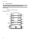
CHAPTER 10 Timer
10.3 Register of 16-bit Timer (Timer 0 to 4)
Register configuration/functions of 16-bit timer (timer 0 to 4) is shown.
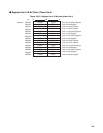
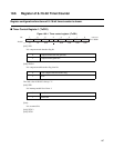
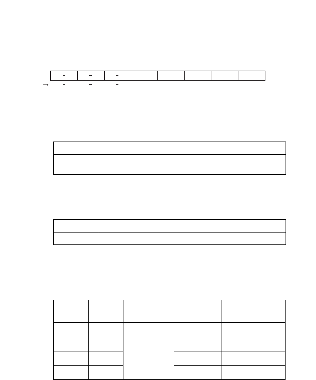
■ Timer Control Register L (TxCRL)
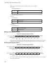
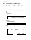
Figure 10.3-1 Timer control register L (TxCRL)
[bit7 to 5]:
It is an unused bit.
[bit4]:LREQ
It is timer data load request bit.
Always read "0" at reading.
[bit3]:LFLG
It is timer data load complete flag bit.
[bit2]:TC1
[bit1]:TC0
There are clock source selection bit. Timer 0 to 4 is as follow.
7 6 5 4 3 2 1 0
---0 0000
B
Initial value
bit
Access
LREQ LFLG TC1 TC0 TSTR
R/W R/W R/W R/WR
0 None
1
Load request is performed timer data to compare latch and output
compare data to output latch.
0 Timer data load complete.
1 Timer data load does not complete.
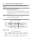
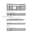
Table 10.3-1 Timer 0 to 3
TC1 TC0 Selection Clock
Clock cycle time
(fch:@20MHz)
0 0
Internal clock
2
4
/fch (FRC3)
0.8 µs
0 1
2
6
/fch (FRC5)
3.2 µs
1 0
2
8
/fch (FRC7)
12.8 µs
1 1
2
10
/fch (FRC9)
51.2 µs