47
3.9.2 Interrupt Stack Operation
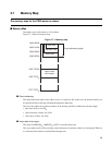
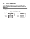
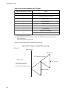
The value of PC and PS is saved and revived in the area shown by SSP. After an
interrupt, PC is stored in the address indicated by the SSP, and PS is stored in the
address (SSP+4).
■ Interrupt Stack
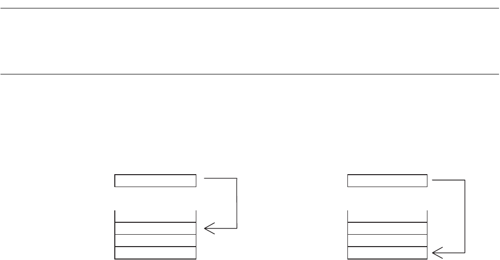
Figure 3.9-1 shows the example of the interrupt stack.
Figure 3.9-1 Interrupt stack operation diagram
[Example] [Befor interrupt] [After interrupt]
SSP SSP
Memory
80000000
H
7FFFFFFC
H
PS
7FFFFFF8
H
7FFFFFF8
H
80000000
H
80000000
H
7FFFFFFC
H
7FFFFFF8
H
PC


