ii
■ Organization of This Document
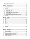
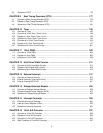
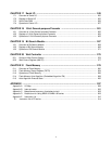
This manual contains the following 21 chapters and an appendix.
CHAPTER 1 Overview of MB91191/MB91192 Series
This chapter includes basic explanations including features of the MB91191/MB91192 series, block
diagrams, and a function outline.
CHAPTER 2 Handling Devices
This chapter describes points to note when using the MB91191/MB91192 series.
CHAPTER 3 CPU
This chapter provides basic explanations for such elements as the architecture, specifications, and
commands, etc., required to understand the CPU core functions of the FR series.
CHAPTER 4 External Bus Interface
This chapter describes an outline of the external bus interface, the register configuration/functions, the
bus operation, and the bus timing, and program examples for the bus operation are explained.
CHAPTER 5 I/O Port
This chapter describes an outline of the I/O port and the register configuration/functions.
CHAPTER 6 FG Input
This chapter describes an outline of the FG input section, the register configuration/functions, and their
operation.
CHAPTER 7 FRC Capture
This chapter describes an outline of the FRC capture section, the register configuration/functions, and
each input section operation.
CHAPTER 8 Programmable Pulse Generator (PPG0, 1)
This chapter describes an outline of the programmable pulse generator (PPG0, 1), the register
configuration/functions, and their operation.
CHAPTER 9 Real Timing Generator (RTG)
This chapter describes an outline of the real timing generator (RTG), the register configuration/
functions, and their operation.
CHAPTER 10 Timer
This chapter describes an outline of the timer section, the register configuration/functions, and timer
section operation.
CHAPTER 11 12-bit PWM
This chapter describes an outline of the PWM, the register configuration/functions, and the PWM
operations.
CHAPTER 12 8-bit Pulse Width Counter
This chapter describes an outline of the 8-bit pulse width counter, the register configuration/functions,
and 8-bit pulse width counter operations.
CHAPTER 13 External Interrupt
External interrupt comprises of the key input interrupt and external interrupt sections. This chapter
describes an outline of the external interrupt 1 (key input circuit) and external interrupt (INT0 to 2), and
the register configuration/functions, and their operation.


