220
CHAPTER 13 External Interrupt
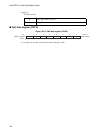
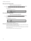
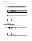
■ Key Input Control Register (KEYC)
Figure 13.2-3 Key input control register (KEYC)
[bit7 to 0]:KIE7 to 0
There are input enable bit of KEY7 to 0.
■ Key Input Status Register (KEYS)
Figure 13.2-4 Key input status register (KEYS)
[bit7 to 0]:KIS7 to 0
There are edge detection flag of KEY7 to 0.
These flags are cleared by the read operation.
■ Operation of External Interrupt 1 (Key Input Circuit)
In order to use the key input, Port A input must be enabled. If Port A input is disabled while key input is
enabled, a key input edge detection interrupt may be generated.
The key input sets the flip-flop when the input signal falling edge is detected. In this case, if the supported
key input is enabled, an interrupt request is generated. The generated interrupt request can be also used to
return from standby status, etc.
Do not use the bit operation command to read the key input status register.
7 6 5 4 3 2 1 0
0000 0000
B
Initial value
bit
Address: 000096
H
R/W R/W R/W R/W R/W R/W R/W R/W
KIE7 KIE6 KIE5 KIE4 KIE3 KIE2 KIE1 KIE0
Access
0 KEY input interdiction
1 KEY input permission
7 6 5 4 3 2 1 0
XXXX XXXX
B
Initial value
bit
Address: 000097
H
KIS7 KIS6 KIS5 KIS4 KIS3 KIS2 KIS1 KIS0
RRRRRRRR
Access
0 None
1 Falling edge detection


