202
CHAPTER 10 Timer
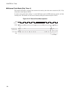
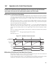
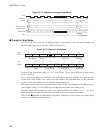
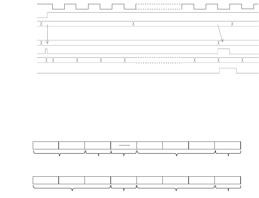
Figure 10.7-2 Operation of external Clock Mode
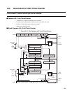
■ Control in 16-bit Mode
The 16-bit mode can be used as the 16-bit timer/counter in the same way as the 8-bit mode by setting each
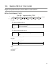
bit of the timer control register (TxCR1, TxCR1) as Figure 10.7-3 .
Figure 10.7-3 Control in 16-bit mode
In terms of the 16-bit mode setting, set "111" to the TCS12, TCS11, and TCS10 bits of timer control
register 1 (TxCR1).
In the 16-bit mode, timers are controlled by the timer control register 0 (TxCR0). As regards the data
register in this case, TxDR1 is the superior byte and TxDR0 is the subordinate byte. For the count data
register, TxCD1 is the superior byte and TxCD0 is the subordinate byte.
The selection of the clock source is performed in the TCS02, TCS01, and TCS00 bits of TxCR0. In order to
start the timer, writing "1" to the TSTR0 bit of TxCR0 clears the counter, and counting starts.
When the counter value matches the compare latch value, the TIF0 bit of TxCR0 is set to "1". As above,
under 16-bit mode, the timer 0 side function can be used as it is in the extended 16-bit format.
Refer to the "■Operation in 8-bit Internal Clock Mode, Operation of 8-bit external clock mode (Event
counter)" for operations under 16-bit mode.
7F
H
7F
H
00
H
01
H
FF
H
02
H
03
H
7E
H
7F
H
00H 01H
00
Indeter-
minate
55
H
FF
H
Compare latch
Counter clear
Count value
ECx
TSTR0=1
TxDR0
TIF0
TFCR0=0(W)
TxCR1 TIF1 TFCLR1 TIE1 TCS12 TCS11 TCS10 TSTR1
No relation Set ot 0 Set to 111 Set ot 0
TxCR0 TIF0 TFCLR0 TIE0 CINV TCS02 TCS01 TCS00 TSTR0
Flag Clock polling Clock select Start/Stop
76543210bit
76543210bit


