201
10.7 Operation of 8-/16-bit Timer/Counter
In terms of 8-/16-bit timer/counter operations, there are controls for the 8-bit internal
clock mode, 8-bit external clock mode (event counter), and 16-bit mode.
■ Operation in 8-bit Internal Clock Mode
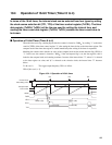
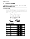
In terms of the 8-bit internal clock mode, the internal clock can be selected from seven types by setting the
clock source selection bit (TCS02, TCS01, TCS00) (TCS12, TCS11, TCS10) of the timer control register
0, 1 (TxCR0, TxCR1). The timer data register 0, 1 (TxDR0, TxDR1) will be the register for setting the
interval time.
When the timer starts up, writing "1" to the timer start bit (TSTR0, TSTR1) of the timer control register
after setting the interval time to the data register clears the counter to "00
H
", and loads the data register
value to the compare latch. Then counting starts.
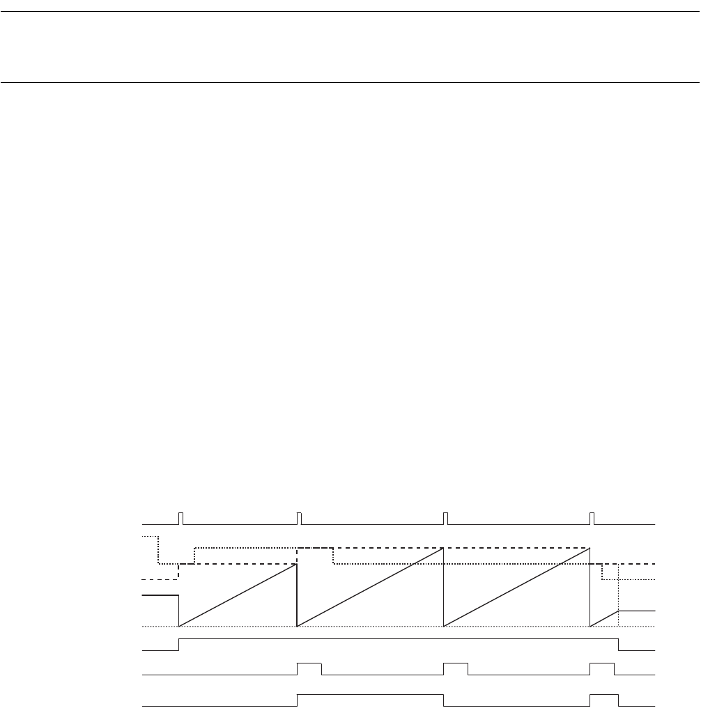
When the counter value matches the compare latch value, "1" is set as the compare match detection flag
(TIF0, TIF1). In this case, the counter is cleared to "00
H
", and the data register value is reloaded to the
compare latch, and counting continues. Also, the toggle output (TxOx) reverses the output per compare
match.
When "n" is selected as the data register set value, and "Φ" is selected as the selection clock, the interval
time "T" becomes below.
T = Φ × (n+1) The toggle output frequency fTO is as follow.
fTO=1/{Φ × (n+1) × 2}
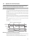
Figure 10.7-1 Operation of Internal clock mode
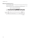
■ Operation of 8-bit External Clock Mode (Event Counter)
The external clock mode is used to select the external clock input using the clock source selection bit
(TCS02, TCS01, TCS00) of the timer control register 0 (TxCR0).
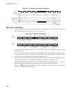
In order to start up the timer, writing "1" to the TxCR0 timer start bit (TSTR0) clears the counter, and then
counting starts. The number of events can be found by reading the count data register (TxCDL).
Counter clear
Data setting value
Compare latch
Count value
0000
H
TSTRx
TIFx
TxOx
TFCRx=0(W)
TFCRx=0(W) TFCRx=0(W)
EQ EQ EQ


