


Configuration
88 UDA2182 Universal Dual Analyzer Product Manual January 2009
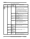
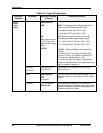
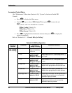
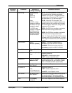
Table 6-11 Logic Configuration
Sub-menu
selection
Parameter Selection or Range
of Setting
Parameter Definition
Type
None (default)
AND
OR
Note: User must set
to “OR” if only one
input source is being
used.
LATCH
None
AND -Turns digital output ON when input IN A
Source and IN B Source are ON. Thus,
If all inputs are ON, then: OUT = ON.
If any input is OFF, then: OUT = OFF.
OR - Monitors Input A Source and Input B
Source to set state of digital output signal.
If A = OFF and B = OFF, then OUT = OFF.
If A = ON and/or B = ON, then: OUT = ON.
LATCH – Sets and Resets Latch state of the
Output.
If A=ON, B=OFF The Output is Latched ON.
If A=OFF, B=ON, The Output is Latched OFF.
If A and B are ON the Output = ON
If A and B are OFF the Output = Latch State.
Power On considerations. The output state of the
latch is cleared on power on.
In A Source
In B Source
Any Digital Signal
See Table 6-4
Input A logic source selections, and Input B logic
source selections
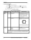
Invert
None (default)
IN A
IN B
In A and B
You can invert Input A or Input B or both. If the
input is inverted, an input line that is ON is seen
as OFF
Logic 1
Logic 2
Logic 3
Logic 4
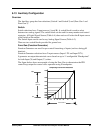
On Delay 0 to 120 seconds
default = 0.0
An on-delay time value up to 120 seconds is
available to prevent momentary logic gate output
actions. Number of seconds the logic gate is true
before activating the Output.