


Inputs and Outputs Wiring
124 UDA2182 Universal Dual Analyzer Product Manual January 2009
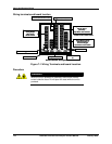
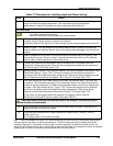
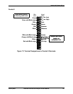
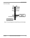
HPW7000
15
14
13
12
11
10
9
8
7
6
5
4
3
2
1
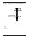
Signal
Name
Wire
Color
Reference
Guard
Glass (or ORP)
RTH Low
RTH High
Black
White
White with Black stripe
Jumper
Clear (center conductor of coax)
Counter
RTH 3
rd
Wire
Red
Clear (center conductor of coax)
Reference cable shield
(White with Green stripe)
to chassis ground screw
Measurement
cable
Thermistor
cable
Reference
cable
Thermistor cable shield
(White with Green stripe)
to chassis ground screw
Some cables have connectors on the leads.
Cut off the connectors, skin and tin the leads
and then wire to the screw terminals on the boards
Measurement
cable shield
(White with Green stripe)
to chassis
ground screw
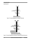
15
14
13
12
11
10
9
8
7
6
5
4
3
2
1
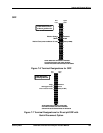
15
14
13
12
11
10
9
8
7
6
5
4
3
2
1
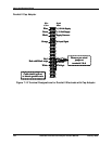
Signal
Name
Wire
Color
Reference
Guard
Glass (or ORP)
RTH Low
RTH High
Black
White
White with Black stripe
Jumper
Clear (center conductor of coax)
Counter
RTH 3
rd
Wire
Red
Clear (center conductor of coax)
Reference cable shield
(White with Green stripe)
to chassis ground screw
Measurement
cable
Thermistor
cable
Reference
cable
Thermistor cable shield
(White with Green stripe)
to chassis ground screw
Some cables have connectors on the leads.
Cut off the connectors, skin and tin the leads
and then wire to the screw terminals on the boards
Measurement
cable shield
(White with Green stripe)
to chassis
ground screw
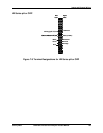
Figure 7-8 Terminal Designations for HPW7000 System