


Appendices
January 2009 UDA2182 Universal Dual Analyzer Product Manual 229
15.15 Appendix N – Sample Tap Electrode Mounting
Recommendations
Overview
Many applications tap a sample from a main process stream and, after the flow has
passed through the measurement manifold, it is discharged to a sink or floor drain.
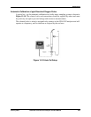
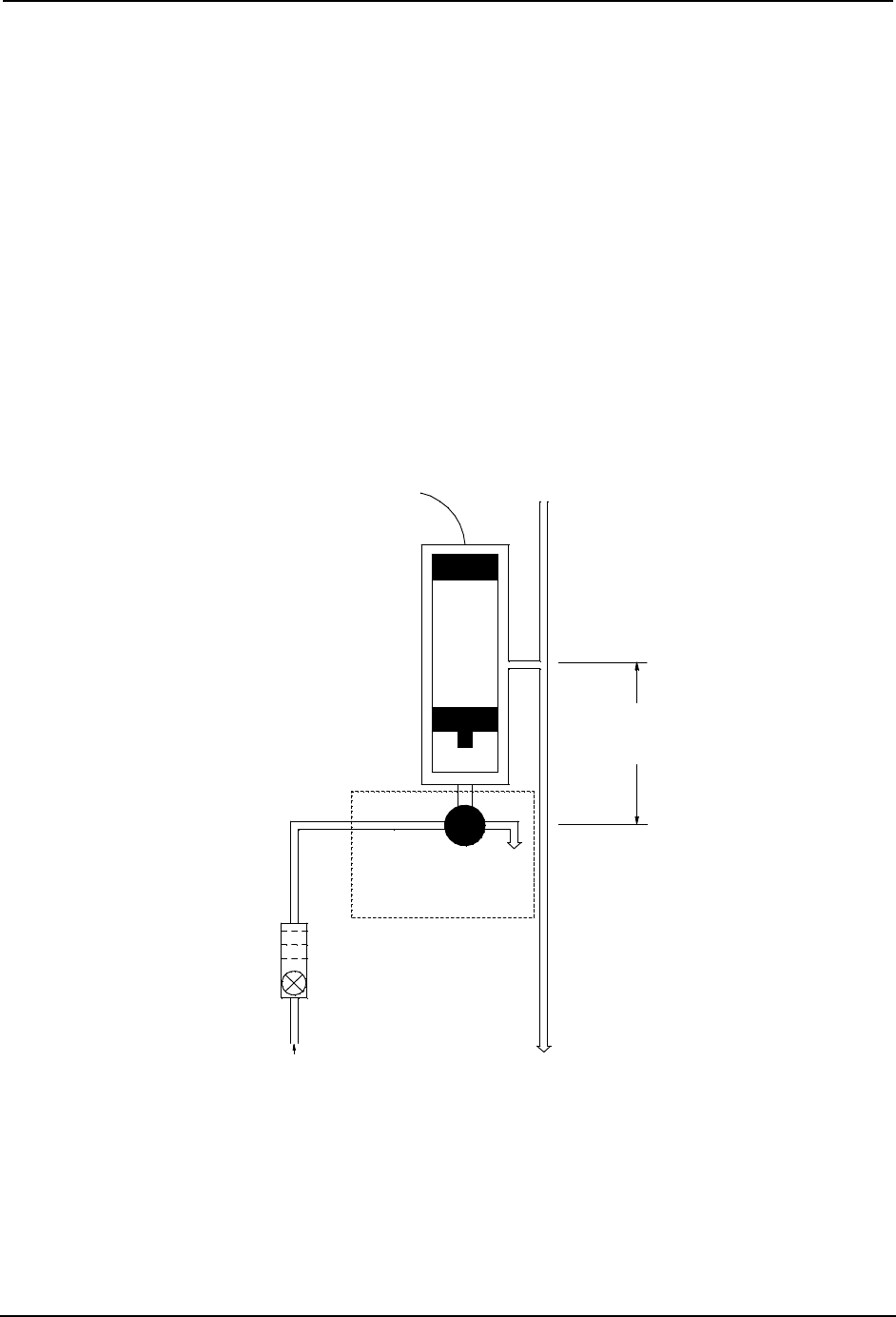
Typical Probe Installation
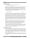
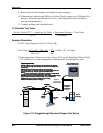
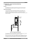
A typical probe installation will find the probe mounted in a flow chamber or tee
arrangement similar to what is shown in Figure 15-8. Key installation features are
provision for flow rate adjustment, a water trap to assure that the probe remains
immersed if sample flow is turned off and means to prevent a below atmospheric pressure
within the manifold.
DRAIN
DRAIN
OPTIONAL 3-WAY
VALVE AND DRAIN
FOR DISSOLVED
OXYGEN INSTALLATIONS
FLOW
FLOW
METER
pH, ORP,
Conductivity
or DO
PROBE
AIR
VENT
3 - 6" Water trap
keeps probe tip we
t
when sample wate
r
is turned off
Air vent prevents vaccuum
in discharge to drain line
avoiding air leaks and
resulting problems.
Figure 15-8 Typical Probe Installation
It is desirable for water to exit the manifold 3 to 6 inches above the sensor tip. This will
insure that the sensor remains immersed if sample flow is turned off.
The air vent extension is sized so normal sample flow does not completely fill this tube.
Its purpose is to prevent negative pressure within the manifold. Without this air vent, if
for example the exit stream is discharged to a floor drain four feet below the manifold,