


Configuration
January 2009 UDA2182 Universal Dual Analyzer Product Manual 59
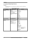
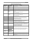
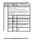
Table 6-3 Analog Signal Sources
Analog Signal Description Definition
Input 1 PV Input 1 Process
Variable
PV Source selection
Input 2 PV Input 2 Process
Variable
PV Source selection
Input 1 Temp Input 1 Temperature Input 1 Temperature Selection
Input 2 Temp Input 2 Temperature Input 2 Temperature Selection
Pharma Out 1 Pharmacopoeia
Output 1
Input 1 Pharmacopia 1 Output (for Conductivity) = percent of USP
stage limit
Output = 100 * pv in uScm / USP stage limit
Valid for Conductivity Input
Pharma Out 2 Pharmacopoeia
Output 2
Input 2 Pharmacopia 2 Output = percent of USP stage limit
Output = 100 * pv in uScm / USP stage limit
Valid for Conductivity Input
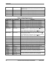
Math 1 Math 1
Math 2 Math 2
Math 3 Math 3
Math 4 Math 4
Math selections can be connected to any Input PV, secondary
variable (Temperature), or Calculated Value. Math blocks include
scaling for the linear selection only.
See Table 6-10 for Math Configuration
Func Gen 1 Function Generator 1
Func Gen 2 Function Generator 2
Generates an output characteristic curve based on up to 11
configurable data points for both input (X) and output values (Y).
Part of the Auxiliary Configuration group.
See Table 6-12 for Function Generator Configuration
Switch 1 Switch 1
Switch 2 Switch 2
Switch selections have 2 input sources (A and B). A switch block is
used to select between two analog signals. The switch block can be
used for many monitor and control strategies. A Digital Signal Source
when active will select the B input source of the switch as the output.
Part of the Auxiliary Configuration group.
See Table 6-12 for Switch Configuration
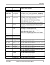
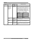
Sum* Input 1 + Input 2
Difference* Input 1 – Input 2
Ratio* Input 1 / Input 2
%Passage* Min(Input 1 or 2)
Max(Input 1 or 2)
*100
% Rejection* (1-Min(Input 1 or 2)/
Max(Input1 or 2))
*100
The availability of calculated variables in the list of available sources
for alarms, math and control and for status display is determined by
similarity of units of measure between the two input boards.
Cation Value pH Value Calculated pH value from differential conductivity
PID Out 1 PID Output 1 PID 1 Output in percent (0 to 100). Normally connected to a
proportional current (Current Type) or time proportional or frequency
proportional relay.