


Configuration
January 2009 UDA2182 Universal Dual Analyzer Product Manual 81
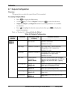
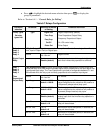
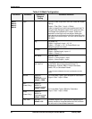
6.9 Alarms Configuration
Overview
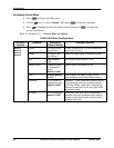
Alarm 1 through 4
Alarm selections can be connected to any Analog Signal (Table 6-3 Analog Signal
Sources). Each alarm supports a setpoint type and value.
Alarm selections generate front panel alerts, support latching/acknowledge, with on delay
timers. Select any Digital signal (Table 6-4 Digital Signal Sources) to disable the Alarm
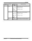
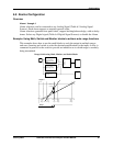
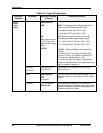
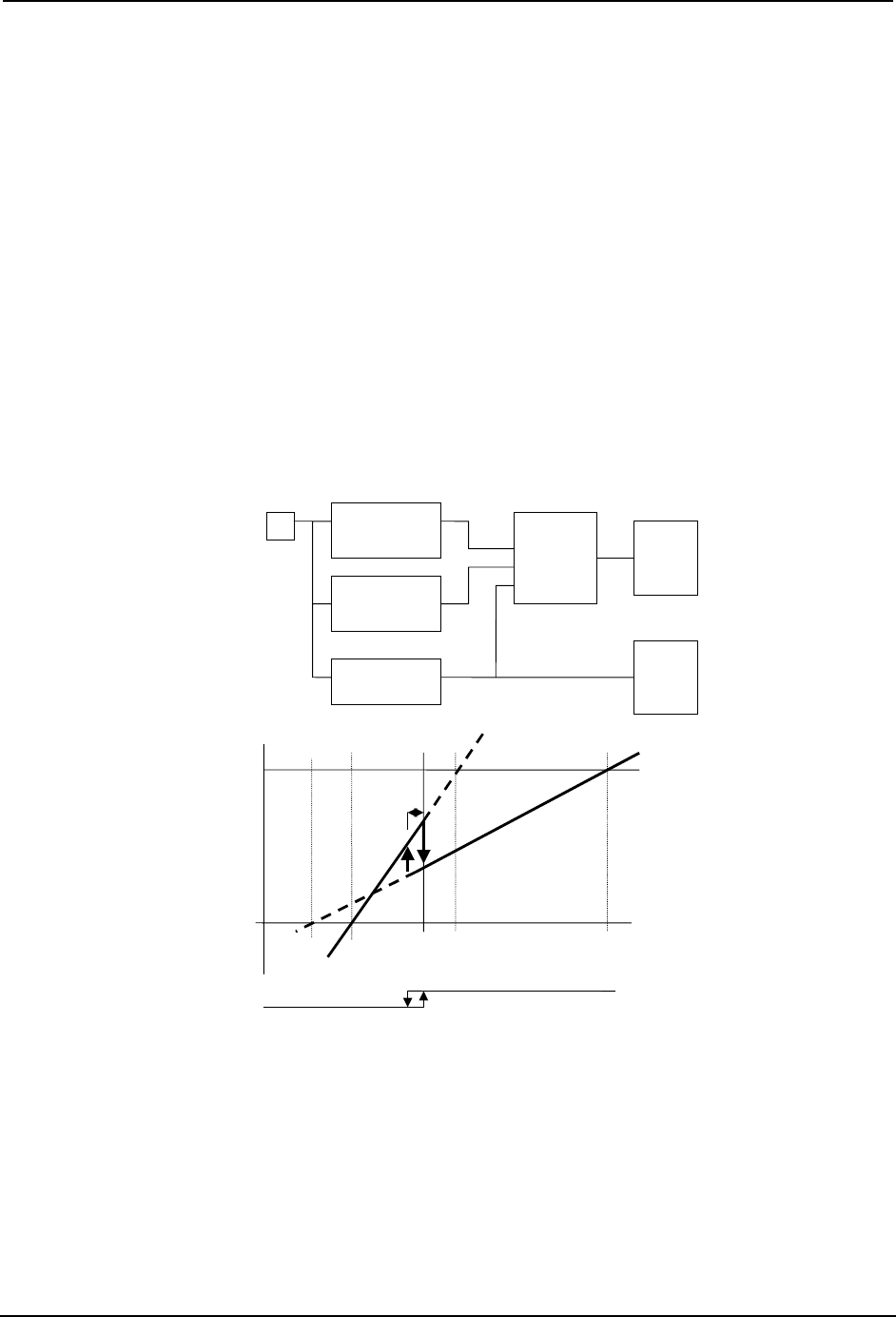
Example: Using Math, Switch and Monitor blocks to achieve auto range functions
This example shows how to use the math blocks to scale the output in multiple ranges
and uses a monitor and switch to select the desired amplification for the input. A relay is
connected in parallel to the switch to provide an indication as to which range is currently
being transmitted.
Range Switch using Math, Monitor, and Switch Blocks
Math 1
(x – low range) \
(high range – low
range)
Monitor 1
High, SP = V
Switch 1
InA
InB
SW
Output 1
Relay 1
Math 2
(x – low range) \
(high range – low
range)
X
Output 1
x
Math 1
Low
Range
Math 2
Low
Range
100
0
Math 2
High
Range
Math 1
High
Range
Monitor 1
SP
High
Monitor 1
Hysterisis
Relay 1