


Appendices
January 2009 UDA2182 Universal Dual Analyzer Product Manual 223
15.11 Appendix J – Discussion on Chemical Interferences on
Measured DO Currents
There are four contributors to measured current:
Faradaic Currents
Faradaic currents are those resulting from oxidation or reduction of chemical species.
The reduction of oxygen to water, the oxidation of water to oxygen, and the oxidation of
hydrogen, hydrazine or sulfur dioxide, are examples of Faradaic currents.
Residual Currents
Residual currents are unwanted Faradaic currents caused by impurities in the probe
electrolyte. These impurities are metals (e.g. lead, zinc) in electrolyte reagents, which are
capable of being reduced at the cathode and give rise to zero offset currents at “zero ppb
oxygen”.
Electrode Conditioning Currents
The platinum cathode and anode materials are actually made up of conducting platinum
oxides. These oxides exist at the molecular level. The actual platinum surface state
strongly affects the observed Faradaic currents. Before methods of wire conditioning
were established, upwards of 96 hours was needed to allow these conditioning currents to
stabilize. Once wire-conditioning methods were established, it now takes approximately
24 hours for these conditioning currents to completely stabilize. Electrode conditioning
currents occur on first probe power-ups, following power interruptions of more than 1
second (back-up power is provided for the probe to prevent this current during a power
outage of 1 hour or less) and following a Probe Bias test.
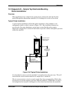
Charging Currents
The Dissolved Oxygen (DO) probe consists of closely spaced bi-filar platinum windings
separated by a high dielectric constant material. This is a description of a capacitor; the
capacitance of a DO probe is in the hundreds if microFarads. When the probe is scanned
during a Probe Bias Test(PBT) at 25mV/sec, an appreciable charging current is
observed. This is equivalent to several hundred ppb dissolved oxygen.
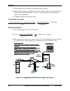
The purpose of the PBT is to verify the optimum operating range of the current/voltage
curve. It further allows one to determine if a reference shift has occurred. Most
importantly, it allows one to select to identify a new bias point, if one is needed. To
employ this diagnostic, you should be in air or air saturated water (ppm current is in uA
range). A PBT should not be performed in a ppb application (ppb current is in nA range),
due to charging and electrode currents being at a maximum value (µA range) during one
of these scans. Furthermore, the final current rise during the PBT produces both
hydrogen and oxygen gases within the probe. Time is needed before these gases can re-
establish equilibrium with the outside sample. Therefore, the PBT should be limited to air
level conditions and adequate time should be allowed for probe recovery following a
PBT.