


Unpacking
January 2009 UDA2182 Universal Dual Analyzer Product Manual 11
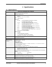
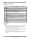
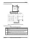
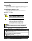
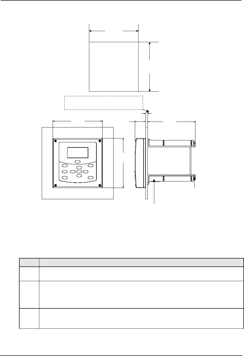
Panel Mounting Dimensions
156
[6.14]
156
[6.14]
152
[5.98]
33.5
[1.32]
138
[5.43]
+1
-0
+.04
-0
138
[5.43]
+1
-0
+.04
-0
Panel Cutout
(4) 22.22[.87] holes for
lead wires and conduit fittings
(conduit fittings supplied by user)
Customer will need to provide a rear panel support
plate to maintain NEMA4 protection if primary
panel thickness is less that 2.3mm [0.09”] thick
CUSTOMER PANEL
1.6[.06] to 6.35 MAX[0.25]
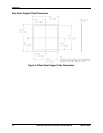
156
[6.14]
156
[6.14]
152
[5.98]
33.5
[1.32]
138
[5.43]
+1
-0
+.04
-0
138
[5.43]
+1
-0
+.04
-0
138
[5.43]
+1
-0
+.04
-0
138
[5.43]
+1
-0
+.04
-0
Panel Cutout
(4) 22.22[.87] holes for
lead wires and conduit fittings
(conduit fittings supplied by user)
Customer will need to provide a rear panel support
plate to maintain NEMA4 protection if primary
panel thickness is less that 2.3mm [0.09”] thick
CUSTOMER PANEL
1.6[.06] to 6.35 MAX[0.25]
Figure 3-1 Panel Mounting Dimensions (not to scale)
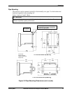
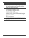
Panel Mounting Procedure
Table 3-2 Panel Mounting Procedure
Step Action
1
Mark and cut out the analyzer hole in the panel according to the dimension information
in Figure 3-1.
2
Orient the case properly and slide it through the panel hole from the front.
Customer will need to provide a rear panel support plate to maintain NEMA4
protection if primary panel thickness is less that 2.3mm [0.09”] thick –
See Figure 3-2.
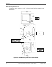
3
Remove the mounting kit from the shipping container and clamp the edges of the
cutout between the case flange and the supplied U-bracket that is fastened to the rear
of the case using (2) M5 X 16mm long screws and (2) M5 lock washers supplied.