


Configuration
78 UDA2182 Universal Dual Analyzer Product Manual January 2009
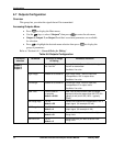
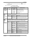
Sub-menu
selection
Parameter Selection or Range
of Setting
Parameter Definition
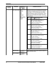
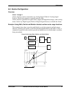
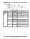
Frequency proportional output is a form of a process variable transmitter or control output
that pulses the relay as a pulse rate that is proportional to the input signal over a configured
relay range. The maximum frequency is set by the cycle time that is configurable between
0.1 and 999 seconds. The pulse duration is fixed and configured in seconds by an on time
parameter.
Source
Any Analog Signal
See Table 6-3
PV Source
High Range -99999 to 99999
default = 100.00
The high range is the PV based engineering unit
value configured as the value that will produce a
100 percent (Maximum Frequency) duty cycle.
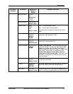
Low Range -99999 to 99999
default = 0.00
The low range is the PV based engineering unit
value configured as the value that will produce a
0 percent (always inactive) duty cycle.
Invert Enable
Disable (default)
Inverts the proportional range of the applied
analog input such that inverse relay operation is
achieved.
Cycle Time 0 to 999
default = 10
Sets the Cycle Time of the maximum output
frequency.
Max Freq=1/Cycle Time
Freq Output = Max Freq * (% Input/100)
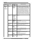
For example:
Freq Output (100%)=Max Freq * 1
Freq Ouput (50%)= Max Freq * .5
Freq Ouput (25%)=Max Freq * .25
Relay 1
Relay 2
Relay 3
Relay 4
Frequency
Proportional
Output Relay
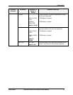
On Time
0.0 to 999
default = 5
Sets the pulse duration. This value should be
less than the cycle time for proper operation.
Typically this value is used to control the pulse
duration for the finial output control element.